Commutation cell, power converter and compensation circuit having dynamically controlled voltage gains

A technology of power converter and reversing unit, which is applied in the direction of converting DC power input to DC power output, converting AC power input to DC power output, electronic switches, etc.

Active Publication Date: 2016-07-27
TM4 INC
View PDF4 Cites 1 Cited by
  • Summary
  • Abstract
  • Description
  • Claims
  • Application Information

AI Technical Summary

Problems solved by technology

In this way, conventional commutation units operate

Method used


Image

  • Commutation cell, power converter and compensation circuit having dynamically controlled voltage gains
  • Commutation cell, power converter and compensation circuit having dynamically controlled voltage gains
  • Commutation cell, power converter and compensation circuit having dynamically controlled voltage gains

Examples


Embodiment Construction

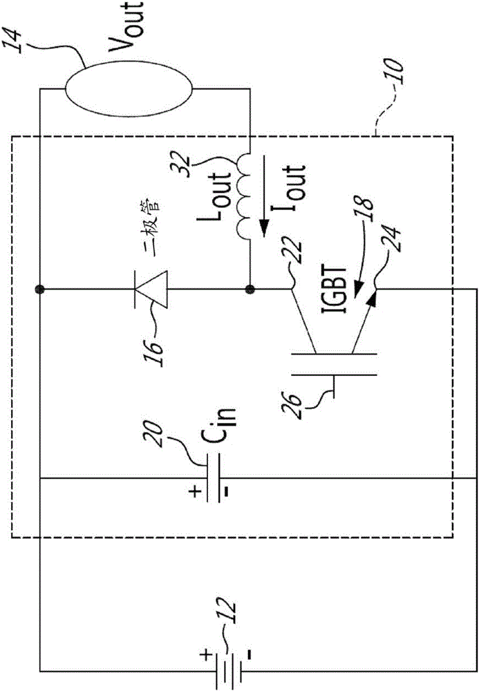
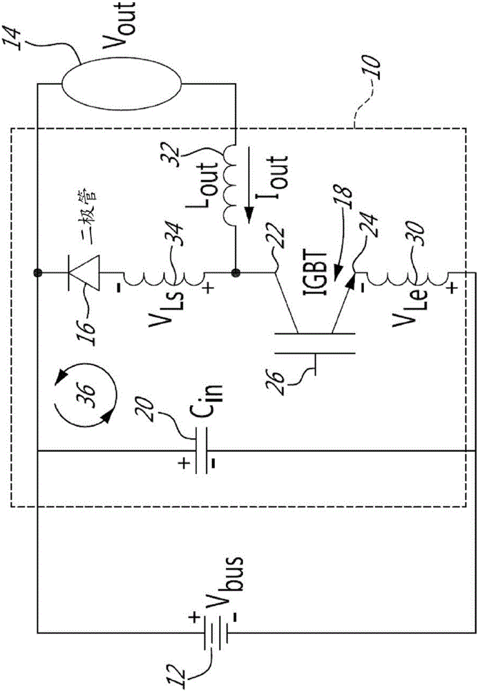
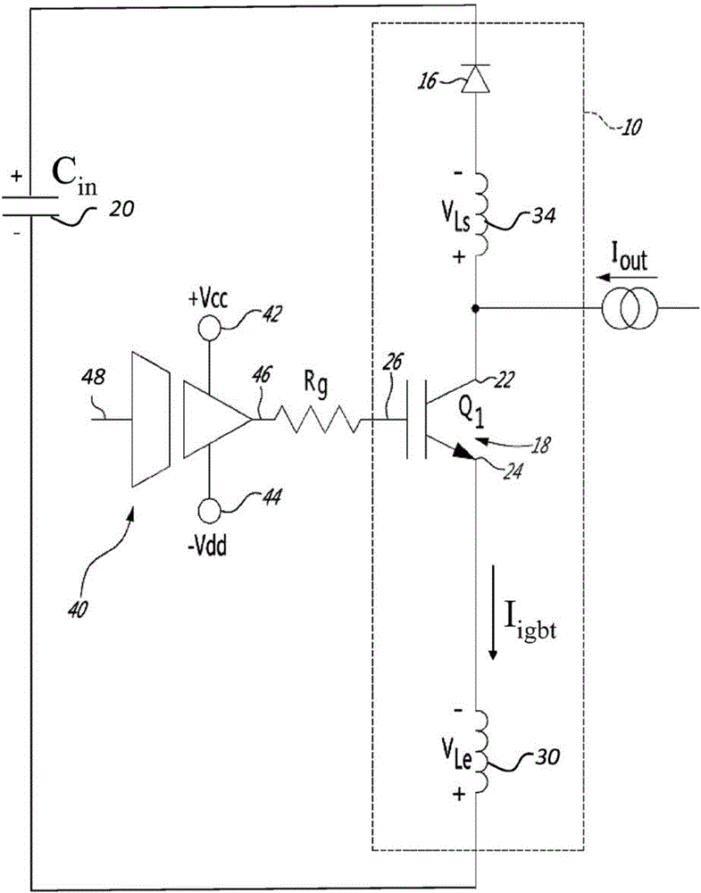
[0037] Aspects of the present disclosure generally address one or more of the problems of overvoltage present in commutation units and power converters when switching.

[0038] Circuits in the commutation unit operable to limit overvoltage, especially when the IGBT is turned off, are described in International Patent Publication No. WO2013 / 082705A1, International Patent Application No. PCT / CA2013 / 000805, US Provisional Application No. 61 / 808,254, 61 / 898,502 and 61 / 904,038, and in http: / / www.advbe.com / docs / DeciElec2013-Jean_Marc_Cyr-TM4.pdf Available "ReducingswitchinglossesandincreasingIGBTdriveefficiencywithReflex TM gated driver technology", the authors in their entirety being Jean-Marc Cyr et al., the disclosures of which are hereby incorporated by reference.

[0039] The present technique provides control over overvoltage and switching losses when the power electronic switches of the commutation unit are turned off. The circuits and methods presented here are generally ...


PUM


Abstract

The present disclosure relates to a commutation cell configured for limiting switching overvoltage. The commutation cell includes a power electronic switch having a parasitic emitter inductance through which a voltage is generated upon turning off of the power electronic switch. The commutation cell also includes a dynamically controlled compensation circuit connected to the parasitic emitter inductance. The compensation circuit applies a controllable portion of the voltage generated through the parasitic emitter inductance at turn-off of the power electronic switch to control the voltage generated through the parasitic emitter inductance. A power converter comprising a pair of commutation cells and a compensation circuit of the commutation cell are also disclosed.

Description

technical field [0001] The present disclosure relates to the field of power electronics. More specifically, the present disclosure relates to a commutation cell configured to limit switching overvoltage upon turn-off of a power electronic switch. The present disclosure further relates to a dynamically controlled compensation circuit for use in a commutation unit, and a power converter comprising a commutation unit with a dynamically controlled compensation circuit. Background technique [0002] Commutation units are commonly used in power electronic systems that require the transformation of a voltage source, including both DC-DC converters and DC-AC converters, commonly referred to as inverters . With limited space reserved for power converter circuits such as those used in electric and / or electric hybrid vehicle applications, and given the high cost of semiconductors, the need for integration of these commutation units increases. [0003] A known way of reducing the spa...

Claims


Application Information

Patent Timeline
IPC IPC(8): H02M1/08H03K17/16H02M1/34
CPCH02M1/08H02M3/156H02M7/217H03K17/04H03K17/166H02M1/344H02M1/32H02M7/537H03K17/081
Inventor C.普罗诺沃斯特J-M.西尔
Owner TM4 INC
Why Eureka
Try Eureka