Leakage prevention type sucker hook
A suction cup and leak-proof technology, which is applied in the direction of suction cups, connecting components, and other household appliances, can solve the problems of poor safety and achieve the effect of improving safety
- Summary
- Abstract
- Description
- Claims
- Application Information
AI Technical Summary
Problems solved by technology
Method used
Image

Examples
Embodiment Construction
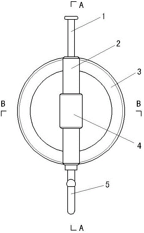
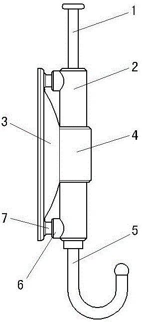
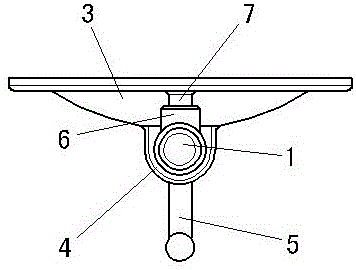
[0018] exist figure 1 , figure 2 , image 3 , Figure 4 , Figure 5 , Figure 6 Among them, the syringe 2 has a barrel-shaped structure, the hook 5 is connected to the lower end of the syringe 2, an upper socket 6 is arranged on the outer wall of the upper end of the syringe 2, and a lower socket 6 is arranged on the outer wall of the lower end of the syringe 2, Through holes communicating with the syringe 2 are opened in the two sockets 6 . The piston 11 is arranged in the syringe 2, and several sealing rings 12 are arranged on the piston 11. The lower end of the driving rod 1 extends into the syringe 2 and is connected with the upper end of the piston 11. The suction cup 3 is a disc-shaped structure, and the suction cup 3 is made of an elastic material. The support ring 4 is connected to the dome end of the outer surface of the suction cup 3. On the inner surface of the suction cup 3, an annular ring is provided along the edge of the suction cup 3 port. The anti-leaka...
PUM
 Abstract
Description
Claims
Application Information