Exoskeleton robot shoulder joint design method based on four-connecting-rod mechanism

A technology of four-bar linkage mechanism and robot shoulder, which is applied in the direction of manipulators, program-controlled manipulators, joints, etc., can solve the problems of cost increase, affecting the wearer's comfort, the robot's range of motion, complex structure, etc., and achieve the effect of cost increase

Active Publication Date: 2016-08-03
SHANDONG MINGYUAN INTELLIGENT EQUIP TECH CO LTD +1
View PDF6 Cites 2 Cited by
  • Summary
  • Abstract
  • Description
  • Claims
  • Application Information

AI Technical Summary

Problems solved by technology

However, if no additional structure is added at all, the shoulder joint movement will be limited, which will affect the comfort of the wearer and the range of motion of the robot.
[0005] To sum up, if the clavicle is fixed when designing the exoskeleton, the wearer will have obvious pressure on the shoulder when the arm is abducted, and the lifting range of the arm will be greatly limited. Long-term wear may even cause shoulder pain. lesion
If a power unit is added separately for the clavicle, the cost will increase significantly, the weight will increase, and the structure will be complicated and difficult to process and assemble

Method used


Image

  • Exoskeleton robot shoulder joint design method based on four-connecting-rod mechanism
  • Exoskeleton robot shoulder joint design method based on four-connecting-rod mechanism
  • Exoskeleton robot shoulder joint design method based on four-connecting-rod mechanism

Examples


Embodiment Construction

[0029] specific implementation plan

[0030] The present invention will be further described in detail below through specific embodiments in conjunction with the accompanying drawings.

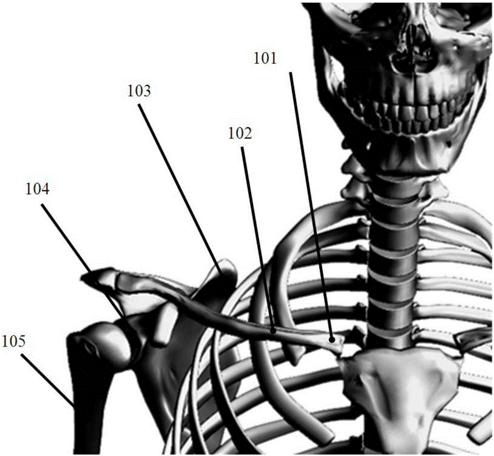
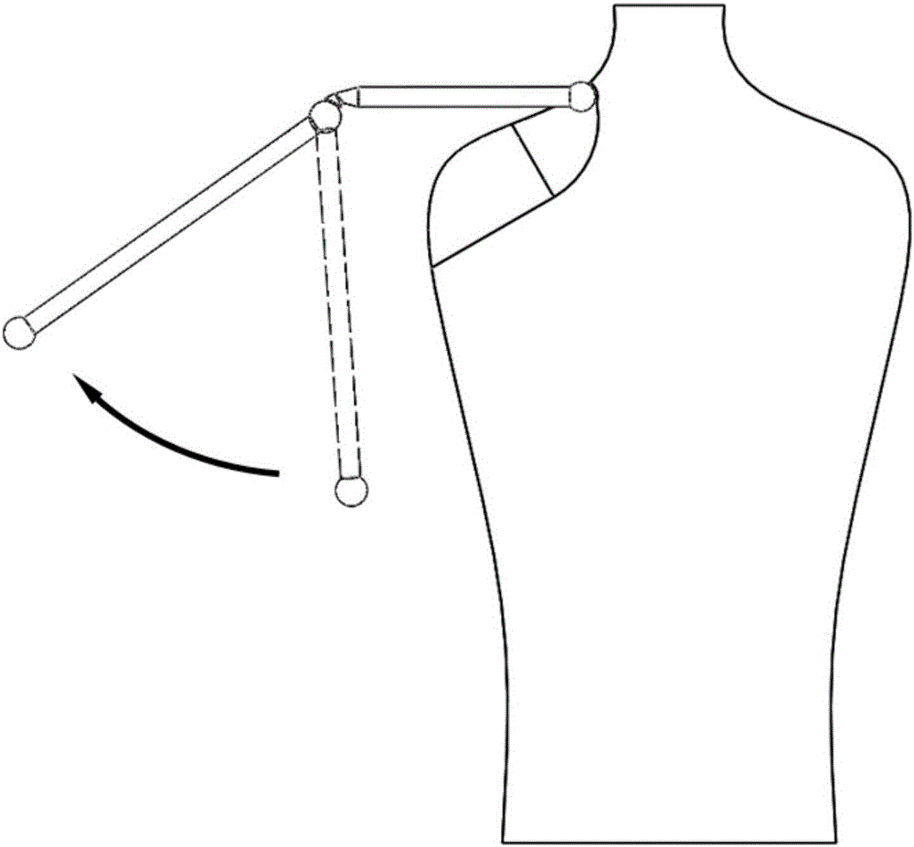
[0031] Because the frequency of the clavicle swinging back and forth is far less than that of the up and down swing, and the amplitude of the back and forth swing is also very small, the present invention ignores the clavicle swing back and forth and only considers the up and down swing. In other words, a set of power actuators will not be used to drive the parts of the exoskeleton to cooperate with the clavicle to swing back and forth.

[0032] The scheme of the present invention roughly divides following several steps:

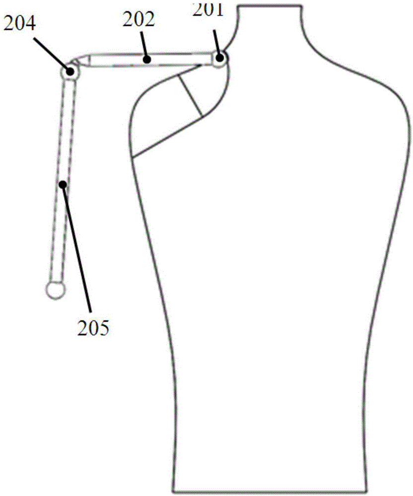
[0033] The first step is to measure the length of the wearer's clavicle and humerus, and try to find the center point of the joint ball head as the endpoint.

[0034] In the second step, the wearer stands upright, with both arms hanging down naturally, and the humerus is v...


PUM


Abstract

The invention provides a method for designing a shoulder joint by using a four-connecting-rod mechanism. The method includes the steps that the position of the shoulder joint when the two arms naturally droop is recorded, and the humerus is marked to be C1B1; the two arms are unbent to outwards extend naturally until the humerus is located in the horizontal direction, the offset of a new position of the shoulder joint relative to the position of the shoulder joint in the last step is recorded, and the humerus is marked to be C2B2; a drawing is made to solve the four-connecting-rod mechanism, and the upper end of the C1B1 is lengthened to a point X1 to serve as a first hinge point of the four-connecting-rod mechanism; another point Y1 on the C1B1 is selected to serve as a second hinge point of the four-connecting-rod mechanism; two corresponding points X2 and Y2 are found on the humerus C2B2; an arc X1X2 is made with the X1 and the X2 as the two end points, the circle center of the arc is located at a point V, another arc Y1Y2 is made with the Y1 and the Y2 as two end points, the circle center of the arc is located at a point U, and the U and the V are the other two hinge points of the four-connecting-rod mechanism; and a line segment UV is made, and the line segment UV represents a rack of the four-connecting-rod mechanism. By means of the method, the shoulder joint and clavicle linkage motion manner can be supported without additionally arranging extra power components such as a motor and a reduction gear.

Description

technical field [0001] The invention relates to the technical field of exoskeleton robots, in particular to a design method for the shoulder joint of an exoskeleton robot based on a four-bar linkage mechanism. Background technique [0002] The structure of the human shoulder is complex, consisting of the clavicle, scapula and humerus in series. The humerus can flexibly rotate around the shoulder joint in three degrees of freedom, while the shoulder joint itself is supported by the clavicle and can move around the sternoclavicular joint in two degrees of freedom. [0003] Taking the right side of the body as an example, attach figure 1 Shows the skeletal structure of the human body above the shoulder. The series joint chain composed of sternum, sternoclavicular joint 101, clavicle 102, scapula 103, shoulder joint 104, and humerus 105 is the basic support structure for upper limb movement. This structure can be approximated as figure 2 In the rod model shown, the sternocl...

Claims


Application Information

Patent Timeline
Patent Type & Authority Applications(China)
IPC IPC(8): B25J9/00B25J17/00
CPCB25J9/0006B25J17/00
Inventor 杨祎航潘华
Owner SHANDONG MINGYUAN INTELLIGENT EQUIP TECH CO LTD
Why Eureka
Try Eureka