Split combined type tower crane wall attaching frame and installation method thereof

A combined type and wall-mounted technology, which is applied to cranes and other directions, can solve the problems that the shaft cannot be reused, has no applicability, and the shaft is shortened, so as to improve the tensile strength and structural stability, ensure stability, The effect of improving the efficiency of use

Inactive Publication Date: 2016-08-03
温州中宏建筑设备有限公司
View PDF6 Cites 8 Cited by
  • Summary
  • Abstract
  • Description
  • Claims
  • Application Information

AI Technical Summary

Problems solved by technology

[0004] When the tower crane exceeds its independent height, a wall-attached device should be erected to increase the stability of the tower crane. The wall-attached device should be erected in accordance with the requirements of the tower crane manual. The distance between the attached walls and the free height above the wall-attached point cannot exceed arbitrarily. Long and extra-long attached wall supports should be designed separately and have calculation books to check the strength and stability. The attached frame should be kept horizontal and fixed firmly on the same level as the attached rod. The verticality of the tower body below the point is not more than 2/1000, and the verticality above the attachment point is not more than 3/1000. The connection point with the building should be selected on the concrete column or the conc

Method used


Image

  • Split combined type tower crane wall attaching frame and installation method thereof
  • Split combined type tower crane wall attaching frame and installation method thereof
  • Split combined type tower crane wall attaching frame and installation method thereof

Examples


Embodiment Construction

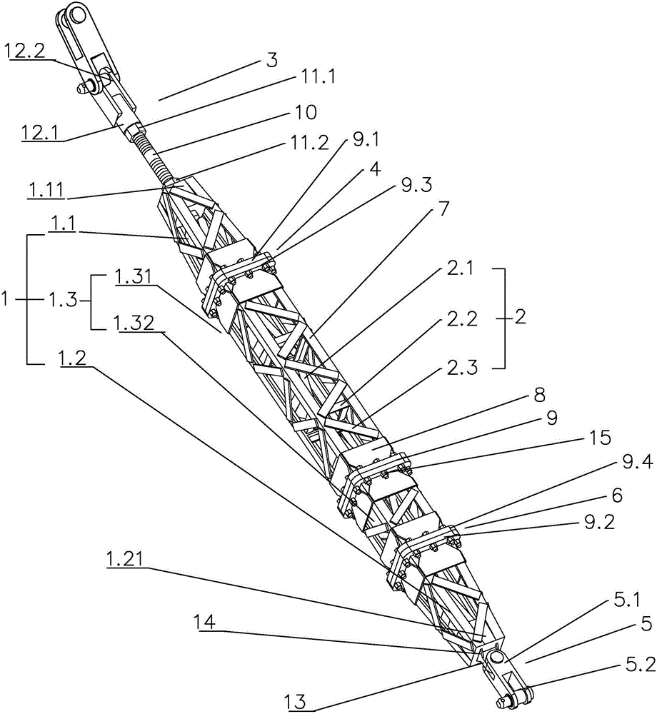
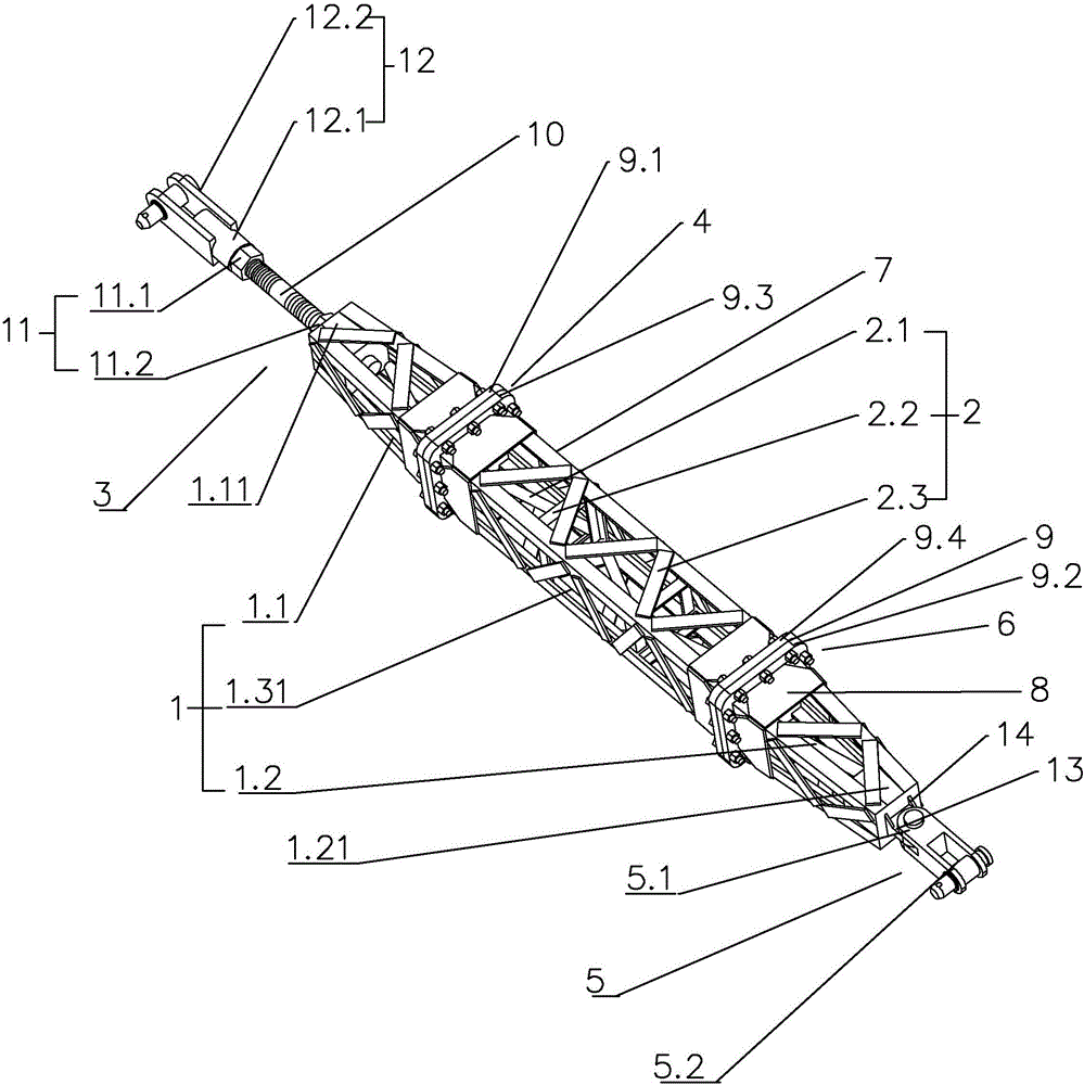
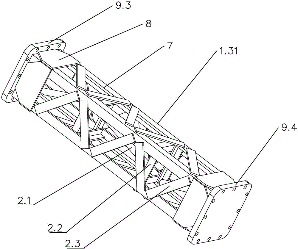
[0043] 1. Reference figure 1 , image 3 , Figure 4 The first embodiment of the present invention will be further described.

[0044] The specific structure and connection relationship of the first embodiment of the split combined tower crane attached wall frame are as follows: a split combined tower crane attached wall frame is connected between the wall body 16 of the building and the tower body 17 of the tower crane, including an attached Wall tie rod body 1, the wall tie rod body 1 includes a first end connecting rod 1.1, a second end connecting rod 1.2 and several shaft sections 1.3 with different lengths connected together, and the shaft section 1.3 includes a long section 1.31 and a short section 1.32, wherein the length of the long section 1.31 is 1 meter or 2 meters or 3 meters or 4 meters or 5 meters, so that in different construction environments, the appropriate long section 1.31 can be selected for splicing according to the specific situation, increasing the app...


PUM

PropertyMeasurementUnit
Lengthaaaaaaaaaa

Abstract

The invention discloses a split combined type tower crane wall attaching frame and an installation method thereof. According to the split combined type tower crane wall attaching frame and the installation method thereof which are provided by the invention, by improving a supporting rod welding structure on a pull rod body, the structural strength of the pull rod body is enhanced, the connecting mode of pull rod connecting rods is improved, the bearing capacity of the pull rod body is enhanced, and the wall attaching pull rod function stability and the installation convenience are ensured. According to the technical scheme, the split combined type tower crane wall attaching frame and the installation method thereof are characterized in that the tower crane wall attaching frame comprises the wall attaching pull rod body which comprises a first tail end connecting rod, a second tail end connecting rod and a plurality of rod body joints different in length, and the first tail end connecting rod, the second tail end connecting rod and the multiple rod body joints are connected together; the first tail end connecting rod, the second tail end connecting rod and the rod body joints are provided with connecting mechanisms used for adjusting the length and the direction and strengthening the stability; and diagonal supporting rods are further arranged on angle iron steel beams of the first tail end connecting rod, angle iron steel beams of the second tail end connecting rod and angle iron steel beams of the rod body joints to enable the wall attaching pull rod body to be rapidly and stably connected between a wall and a tower crane.

Description

technical field [0001] The present invention relates to the technical field of building construction auxiliary equipment and its installation method, more specifically, it relates to a split combined tower crane attached wall frame and its installation method. Background technique [0002] Tower cranes are referred to as tower cranes for short, also known as tower cranes. They originated in Western Europe. They are rotating cranes with movable arms mounted on the top of towering towers. Tower cranes have a large working space and are mainly used for vertical and horizontal transportation of materials in building construction and construction The installation of components is mainly composed of three parts: metal structure, working mechanism and electrical system. The metal structure includes tower body, boom and base, etc.; the working mechanism has four parts: lifting, luffing, turning and walking; the electrical system includes motors. , controllers, power distribution cab...

Claims


Application Information

Patent Timeline
IPC IPC(8): B66C23/62B66C23/88
CPCB66C23/62B66C23/88
Inventor 何忠元邓元军
Owner 温州中宏建筑设备有限公司
Why Eureka
Try Eureka