Lens barrel preventing lens barrel vibration phenomenon and imaging device

A lens barrel, anti-vibration technology, applied in installation, optics, instruments, etc., can solve the problems of lens barrel oscillation and oscillation, and achieve the effect of preventing lens barrel oscillation.

Inactive Publication Date: 2016-08-03
CANON KK
View PDF10 Cites 2 Cited by
  • Summary
  • Abstract
  • Description
  • Claims
  • Application Information

AI Technical Summary

Problems solved by technology

For this reason, when only a part of a plurality of rectilinear mechanisms is engaged, since the vibration that occurs when the lens of the image blur correction mechanism is shifted is amplified, a phenomenon of lens barrel oscillation (oscillation) may occur, especially when the lens is heavy. Oscillation phenomenon is more likely to occur when

Method used


Image

  • Lens barrel preventing lens barrel vibration phenomenon and imaging device
  • Lens barrel preventing lens barrel vibration phenomenon and imaging device
  • Lens barrel preventing lens barrel vibration phenomenon and imaging device

Examples


Embodiment Construction

[0031] Hereinafter, embodiments of the present invention will be described with reference to the drawings.

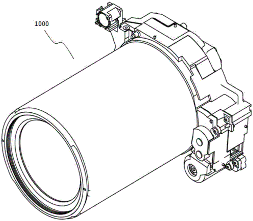
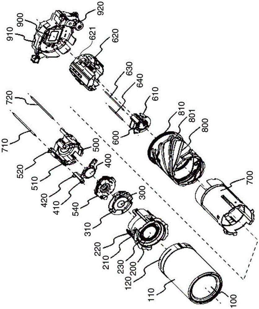
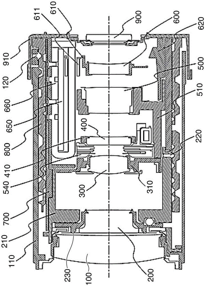
[0032] figure 1 is a perspective view showing a lens barrel according to an embodiment of the present invention. figure 2 is showing figure 1 An exploded perspective view of the lens barrel in . image 3 is showing figure 1 Sectional view of the lens barrel in the retracted position in . Figure 4 is showing figure 1 A cross-sectional view of the lens barrel in shooting position (wide-angle position). Figure 5 is showing figure 1 The cross-sectional view of the lens barrel in is in the shooting position (telephoto position). It should be noted that the lens barrel employed in the examples in this embodiment mode is a zoom-type lens barrel mounted on an imaging device such as a film camera, a digital still camera, or a digital video camera.

[0033] refer to Figure 1 to Figure 5 , the lens barrel 10 according to the present embodiment includes a first group l...


PUM


Abstract

The invention provides a lens barrel preventing lens barrel vibration phenomenon and an imaging device. The lens barrel prevents a vibration phenomenon caused by the vibration when a lens of an image blur correction mechanism moves. A first barrel is joined in a cam barrel and moves in the optical axis direction through the rotation of the cam barrel. A second barrel supports a lens holding member, and is joined in the cam barrel and moves in the optical axis direction through the rotation of the cam barrel. The lens holding member moves in the direction different from the optical axis so as to correct the image blur. The second barrel includes a first vibration proof pin which can be joined with the first barrel in a way of moving in the optical axis direction.

Description

technical field [0001] The present invention relates to a lens barrel having an image blur correction mechanism and an image pickup apparatus, such as a film camera, a digital still camera, or a digital video camera, equipped with the lens barrel. Background technique [0002] Some lens barrels mounted on image pickup devices such as digital cameras etc. are equipped with an image blur correction mechanism that corrects the blur of the subject image formed on the light incident surface by displacing a part of the image pickup lens so that Prevents image degradation caused by camera shake, etc. [0003] There has been proposed a lens barrel having two rectilinear mechanisms, one of which includes a first rectilinear groove and The first straight-forward key, and the other straight-forward mechanism includes a second straight-forward slot and a second straight-forward key (Japanese Patent Laid-Open No. 2012-63755). According to this proposal, the two linear mechanisms have a...

Claims


Application Information

Patent Timeline
Patent Type & Authority Applications(China)
IPC IPC(8): G02B7/04G03B5/00
CPCG02B7/04G03B5/00
Inventor 村上太郎日塔洁足立圭祐寺田修一
Owner CANON KK
Why Eureka
Try Eureka