Novel cavity power divider

A power divider and cavity technology, applied in waveguide devices, electrical components, connecting devices, etc., can solve the problems of limited bandwidth, affecting production efficiency, and high processing precision requirements, so as to reduce processing precision and improve production efficiency. High simulation effect

Inactive Publication Date: 2016-08-03
ANHUI XINBANG PLASTIC CO LTD
View PDF7 Cites 0 Cited by
  • Summary
  • Abstract
  • Description
  • Claims
  • Application Information

AI Technical Summary

Problems solved by technology

[0002] At present, the frequency of the widely used cavity power splitter is between 800-2500MHz, which covers the main frequency of mobile communication, and also covers the general frequency of 3G. Due to the popularization of digital TV, the original analog signal gradually cancels the frequency of 700MHz. The frequency is likely to be used in 3G products. If you want full-band coverage, you need a wider bandwidth bridge and power splitter to cover more frequency bands. Existing power splitters generally use micro Stripline design, its bandwidth is limited, power is also very limited, and now there are some designs of cavity power splitters, but they also face bandwidth limitations, it is difficult to exceed the frequency of 700-2700MHz, because once the bandwidth is widened, the inner conductor will If it needs to be lengthened, it is difficult to guarantee the rigidity of the inner conductor, and it is easy to deform. The difference between the actual trial-produced product and the simulation is huge, and it is difficult to be practical at all, and the processing accuracy is high, which greatly affects the production efficiency.

Method used


Image

  • Novel cavity power divider

Examples


Embodiment Construction

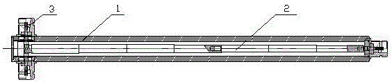
[0009] refer to figure 1 , a new cavity power splitter, which includes a housing 1, a power splitter 2, and a coupler 3, the housing 1 is provided with a power splitter 2, and the two ends of the power splitter 2 are connected to the coupler 3 pins, The shell 1 is connected with the shell of the coupler 3, and the power dividing rod 2 is divided into two sections, and the two sections are connected by threaded studs.

[0010] The power splitter 2 can be provided with 3-5 interfaces to connect with the connector 3 pins respectively.

[0011] In the present invention, a power distribution rod is arranged in the shell, and the power distribution rod is divided into two sections, one section is 1, 2, 3 grades, which is thinner, and the other section is 4, 5, 6, 7 grades, which is thicker, between the two sections It is screwed and connected to form a whole power sub-rod. Since the length of each section is shortened, the processing deformation is very small, thus ensuring the mac...


PUM


Abstract

A novel cavity power divider relates to the technical field of power dividers. The novel cavity power divider comprises a shell, a power dividing rod, and a coupler. The power dividing rod is arranged inside the shell. The two ends of the power dividing rod are connected with the coupler through pins. The shell is connected with a coupler shell. The power dividing rod consists of two sections which are in threaded connection through a stud. According to the invention, an air cavity and an inner conductor are combined, the requirements for coverage bandwidth and power are met, the inner conductor is not easy to deform and is of high degree of simulation, the processing precision required in the process of production is lowered, and the production efficiency is improved.

Description

Technical field: [0001] The invention relates to the technical field of power dividers. Background technique: [0002] At present, the frequency of the widely used cavity power splitter is between 800-2500MHz, which covers the main frequency of mobile communication, and also covers the general frequency of 3G. Due to the popularization of digital TV, the original analog signal gradually cancels the frequency of 700MHz. The frequency is likely to be used in 3G products. If you want full-band coverage, you need a wider bandwidth bridge and power splitter to cover more frequency bands. Existing power splitters generally use micro Stripline design, its bandwidth is limited, power is also very limited, and now there are some designs of cavity power splitters, but they also face bandwidth limitations, it is difficult to exceed the frequency of 700-2700MHz, because once the bandwidth is widened, the inner conductor will If it needs to be lengthened, the rigidity of the inner condu...

Claims


Application Information

Patent Timeline
Patent Type & Authority Applications(China)
IPC IPC(8): H01P5/12
CPCH01P5/12
Inventor 戴爱谷
Owner ANHUI XINBANG PLASTIC CO LTD
Why Eureka
Try Eureka