vacuum cleaner

A technology for vacuum cleaners and vacuum cleaners, applied in the directions of vacuum cleaners, handles, household appliances, etc., can solve the problems of easy wrist fatigue, increase the difficulty of operation, and the user's operating feeling is not very good, and achieve easy cleaning of high places and flexible application. Effect

Active Publication Date: 2019-01-15
TIANKE INTELLIGENT TECH CO LTD
View PDF5 Cites 6 Cited by
  • Summary
  • Abstract
  • Description
  • Claims
  • Application Information

AI Technical Summary

Problems solved by technology

[0002] Hand-held vacuum cleaners are widely used because of their compact structure and small size. Referring to the publication of the invention patent application with the application number 201110293774.4, it can be seen that although the existing hand-held vacuum cleaners have been designed to be very portable, they are not easy to use when cleaning the ground. , because the center of gravity of the body is relatively high, the user's operation feeling is not very good, and the wrist is prone to fatigue
In addition, when it needs to be temporarily stored after use, it cannot be stored upright stably due to the relatively high center of gravity of the body
[0003] There is also a rod-type vacuum cleaner in the prior art. Although the center of gravity is low and convenient to use, it can also be stored upright. However, when cleaning the household surface at a higher position, it will increase the difficulty of operation due to the high center of gravity. The position is even powerless to complete the cleaning action smoothly

Method used


Image

  • vacuum cleaner
  • vacuum cleaner
  • vacuum cleaner

Examples


Embodiment 1

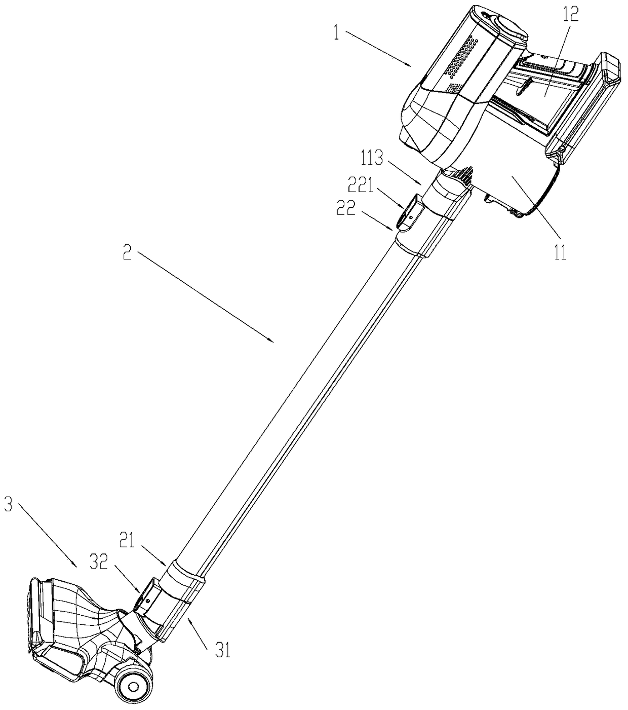
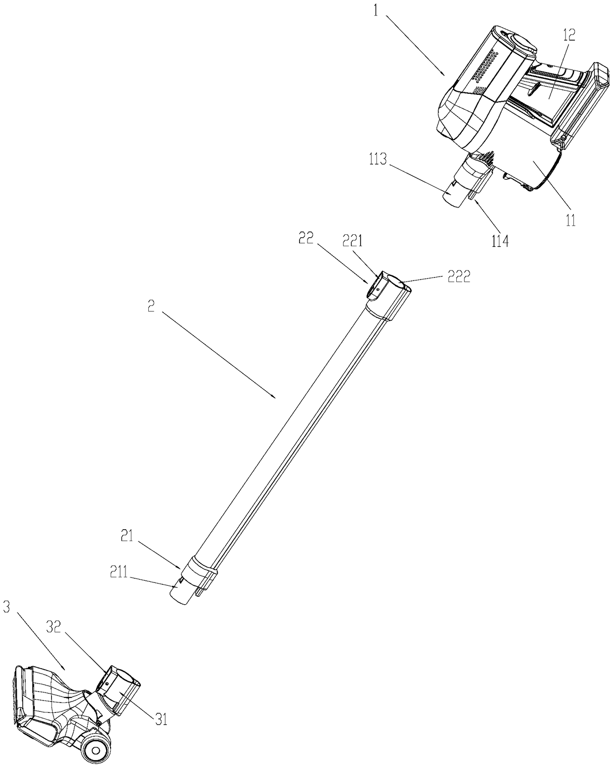
[0029] figure 1 It is a schematic diagram of the first use state of the vacuum cleaner of the present invention. Such as figure 1 As shown, the present invention provides a vacuum cleaner, including a main unit 1, a connecting pipe 2 and a ground brush 3, wherein the main unit 1 includes a body 11 and a handle 12, and in the first use state, the handle 12, the body 11, the connecting pipe 2 and the Ground brushes 3 are connected sequentially. figure 2 for figure 1 Schematic diagram of the exploded structure of each component. Such as figure 2 and combine figure 1 As shown, specifically, in the first use state, the floor brush 3 is detachably connected to the first end 21 of the connecting pipe, and the second end 22 of the connecting pipe relative to the first end 21 of the connecting pipe is detachably connected to the first end 113 of the body. Disassembled connection.

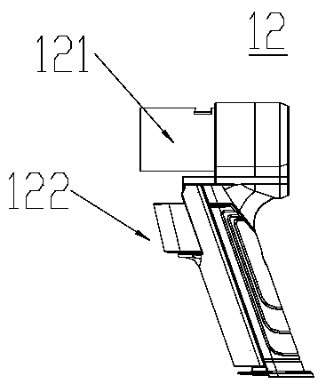
[0030] image 3 It is a structural schematic diagram of the handle of the present invention. S...

Embodiment 2

[0036] Figure 9 It is a combined structure schematic diagram of the second embodiment of the vacuum cleaner of the present invention; Figure 10 for Figure 9 Schematic diagram of the decomposition structure of each component in ; Figure 11 and Figure 12 Respectively are structural schematic diagrams of the fixing clips of the present invention. Such as Figure 9 to Figure 12 As shown, this embodiment is an improvement based on the structure of Embodiment 1, that is, the first use state in this embodiment is the same as Embodiment 1, but the second handle 4 is further added in the second use state. And fixed clip 5 to enhance the stability of the combined structure. The specific connection method is that the second handle 4 is connected with the second end 22 of the connecting pipe, the first end 21 of the connecting pipe is connected with the second end interface 52 of the fixing clip 5, and the first end socket 51 of the fixing clip 5 is connected with the handle of ...


PUM


Abstract

A vacuum cleaner includes a host machine (1), a connection pipe (2) and a floor brush (3); the host machine, the connection pipe and the floor brush are detachably connected; a connection sequence of the host machine and the connection pipe can be changed as needed so as to from two use states: in a first use state, the host machine, the connection pipe and the floor brush are connected successively; and in a second use state, the connection pipe, the host machine and the floor brush are connected successively. According to the vacuum cleaner, all the parts of the vacuum cleaner are detachable and can from various free combination connection manners; various structure combinations are achieved on one type of the vacuum cleaner, the center of gravity of the vacuum cleaner body can be adjusted, and then stable vertical storage can be achieved, and cleaning of high positions is facilitated; and the vacuum cleaner is flexible and variable in use.

Description

technical field [0001] The invention relates to a vacuum cleaner, in particular to a vacuum cleaner, which belongs to the technical field of small household appliances. Background technique [0002] Hand-held vacuum cleaners are widely used because of their compact structure and small size. Referring to the publication of the invention patent application with the application number 201110293774.4, it can be seen that although the existing hand-held vacuum cleaners have been designed to be very portable, they are not easy to use when cleaning the ground. , due to the relatively high center of gravity of the body, the user's operating feeling is not very good, and the wrist is prone to fatigue. In addition, when it needs to be temporarily stored after use, it cannot be stored upright stably due to the relatively high position of the center of gravity of the body. [0003] There is also a rod-type vacuum cleaner in the prior art. Although the center of gravity is low and conve...

Claims


Application Information

Patent Timeline
Patent Type & Authority Patents(China)
IPC IPC(8): A47L5/24A47L9/32A47L9/00
Inventor 蒋晓刚彭中美
Owner TIANKE INTELLIGENT TECH CO LTD
Why Eureka
Try Eureka