
Steel strip reeling machine

A steel strip coil and reel technology, applied in the direction of electromechanical devices, mechanical energy control, electrical components, etc., can solve the problems of poor transmission stability, small application range, single transmission structure, etc., achieve adjustable coiling width, and reduce maintenance difficulty , good transmission stability

Active Publication Date: 2018-11-06
肇庆市森美金属有限公司
View PDF4 Cites 2 Cited by
  • Summary
  • Abstract
  • Description
  • Claims
  • Application Information

AI Technical Summary

Problems solved by technology

[0003] In the prior art, there are still many deficiencies in the steel strip coiler. Its transmission structure is single, the failure rate is high, and the transmission stability is poor. The existing steel strip coiler has a fixed coiling structure and cannot Adjustment, the scope of application is small, and the existing steel strip coiler lacks the center of gravity adjustment function. When coiling the steel strip, accidents are likely to occur due to the center of gravity offset, and the stability is insufficient. Therefore, a new type of steel strip coil is urgently needed. Take the machine to solve the above problems

Method used


Image

  • Steel strip reeling machine
  • Steel strip reeling machine

Examples


Embodiment approach

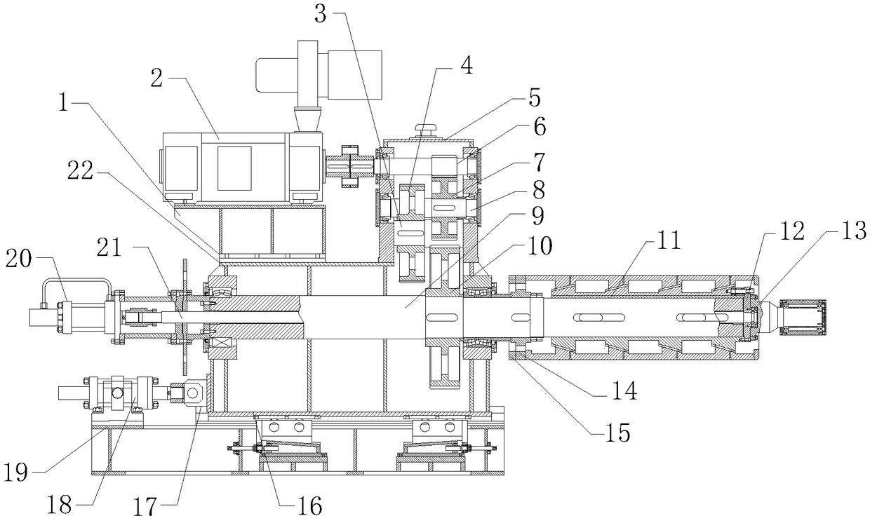
[0024] Specific implementation method: when in use, the staff runs the DC motor 2, and then the DC motor 2 drives the gear shaft 2 6 to rotate in the gearbox 5, the gear shaft 2 6 drives the gear 2 7 to rotate, and the gear 2 7 drives the gear shaft 3 8 Rotate, gear shaft three 8 drives gear one 4 to rotate, gear one 4 drives gear shaft one 3 to rotate, gear shaft one 3 drives gear three 10 to rotate, gear three 10 drives main shaft 9 to rotate, thereby realizes the purpose of main shaft 9 independent rotations.

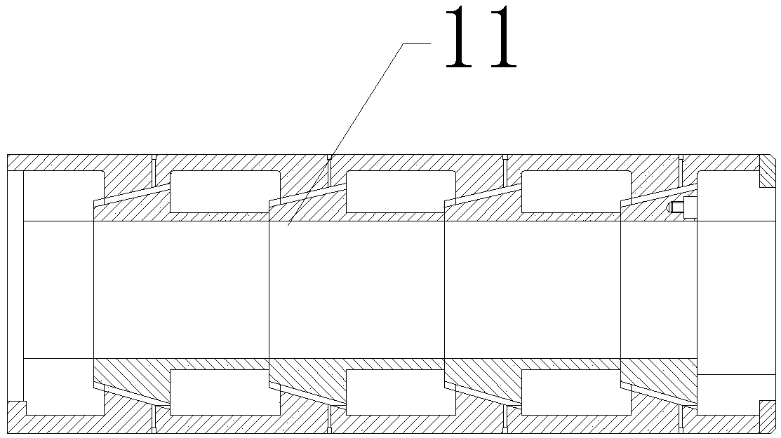
[0025] When the length of the telescopic sleeve 11 needs to be shortened, the staff makes the hydraulic cylinder one 21 shrink, and then the hydraulic cylinder one 21 shrinks to drive the push-pull rod 22 to move to the left in the main shaft 9, and then the push-pull rod 22 drives the retaining sleeve 13 to move to the left. The sleeve 13 squeezes the telescopic sleeve 11 through the baffle plate 12, because the baffle plate 15 is installed on the annular side of the...


PUM


Abstract

The present invention provides a steel strip reeling machine comprising a telescopic sleeve, a retaining sleeve, a push-pull rod, a hydraulic cylinder I, a hydraulic cylinder II, a connecting seat anda lower casing, wherein the hydraulic cylinder I is mounted on the left end surface of a main shaft, the push-pull rod is assembled in the main shaft, the left end of the push-pull rod is connected to the hydraulic cylinder I, the right end of the push-pull rod is installed at the middle position of the left end surface of the retaining sleeve, and the retaining sleeve is threadedly mounted on the right end surface of the telescopic sleeve, and the design of the steel strip reeling machine realizes the adjustable purpose of a reeling structure, the hydraulic cylinder II is fixed on the left side of the upper end surface of a sliding table, the right end of the hydraulic cylinder II is equipped with the connecting seat, the connecting seat is mounted on the left end surface of the lower casing, the lower casing is assembled on the upper end surface of the sliding table, and the lower casing are arranged on the lower side of an upper casing. The of the steel strip reeling machine realizes the purpose of gravity center adjustment. The transmission stability of the steel strip reeling machine is good, the winding width is adjustable, the stability is good, and the center of gravity isadjustable.

Description

technical field [0001] The invention relates to a steel strip coiler, which belongs to the technical field of coilers. Background technique [0002] The coiler is an auxiliary equipment in the rolling mill that coils hot-rolled or cold-rolled steel into a coil. [0003] In the prior art, there are still many deficiencies in the steel strip coiler. Its transmission structure is single, the failure rate is high, and the transmission stability is poor. The existing steel strip coiler has a fixed coiling structure and cannot Adjustment, the scope of application is small, and the existing steel strip coiler lacks the center of gravity adjustment function. When coiling the steel strip, accidents are likely to occur due to the center of gravity offset, and the stability is insufficient. Therefore, a new type of steel strip coil is urgently needed. Take the machine to solve the above problems. Contents of the invention [0004] Aiming at the deficiencies in the prior art, the ob...

Claims


Application Information

Patent Timeline
Patent Type & Authority Applications(China)
IPC IPC(8): B21C47/04B21B15/00H02K7/116
CPCB21B15/00B21B2015/0057B21C47/04H02K7/116
Inventor 肖镇核丁旭东
Owner 肇庆市森美金属有限公司
Learn More