Underground combustion convection heating method
A convective heating and burner technology, which is applied in the direction of mining fluid, earthwork drilling, wellbore/well components, etc., can solve the problems of large heat loss, high cost, low utilization rate, etc., and achieve the effect of reducing heat loss
- Summary
- Abstract
- Description
- Claims
- Application Information
AI Technical Summary
Problems solved by technology
Method used
Image

Examples
Embodiment 1
[0028] Example 1 Underground Open Combustion Convection Heating Method
[0029] Underground open combustion convection heating method, which includes:
[0030] 1) Inject high-pressure air into the casing of the heater well;
[0031] 2) The gas and the combustion-supporting gas are respectively sent into the well casing through the pipeline, at the mining area, mixed and burned in the burner;
[0032] 3) The heat generated by the combustion of the burner heats the high-pressure air injected into the well casing, and mixes with the exhaust gas and air generated by the combustion to form a mixed heating medium;
[0033] 4) The kerogen in the heavy oil or oil shale deposit is pyrolyzed to form oil and gas, and the mixed heating medium is discharged from the oil production well;
[0034] In the step 1), the flame retardant fluid is injected through the pipeline under the burner;
[0035] The flame retardant fluid is CO 2 gas, steam or water.
Embodiment 2
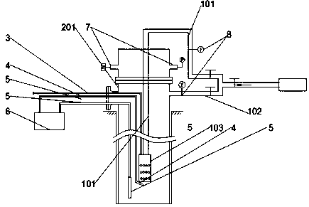
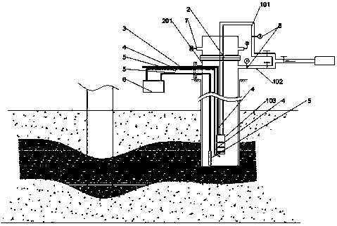
[0036] Embodiment 2 Underground open combustion convection heating device
[0037] Underground open combustion convection heating device, including: well casing air injection pipe 102, combustion-supporting gas delivery pipe 101, gas delivery pipe 3, ignition device 4, burner 103;
[0038] The combustion-supporting gas delivery pipe 101 and the gas delivery pipe 3 are connected to the burner 103, and the burner 103 is arranged in the well casing 201, at the mining area;
[0039] The underground open combustion convection heating device further includes: a temperature monitoring device 5 , an air pressure monitoring device 7 , a flow monitoring device 8 , and a central controller 6 .
Embodiment 3
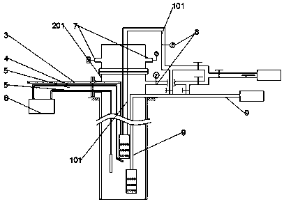
[0040] Embodiment 3 Underground open combustion convection heating device
[0041] Underground open combustion convection heating device, including: well casing air injection pipe 102, combustion-supporting gas delivery pipe 101, gas delivery pipe 3, ignition device 4, burner 103;
[0042] The combustion-supporting gas delivery pipe 101 and the gas delivery pipe 3 are connected to the burner 103, and the burner 103 is arranged in the well casing 201, at the mining area;
[0043] The underground open combustion convection heating device also includes: a temperature monitoring device 5, an air pressure monitoring device 7, a flow monitoring device 8, and a central controller 6;
[0044] The underground open combustion convection heating device further includes: a flame retardant fluid delivery pipe 9, the outlet of which is located at or below the burner 103;
[0045] The upper section of the flame retardant fluid delivery pipe 9 communicates with the combustion-supporting gas ...
PUM
 Abstract
Description
Claims
Application Information
 - R&D
- Intellectual Property
- Life Sciences
- Materials
- Tech Scout
- Unparalleled Data Quality
- Higher Quality Content
- 60% Fewer Hallucinations
Browse by: Latest US Patents, China's latest patents, Technical Efficacy Thesaurus, Application Domain, Technology Topic, Popular Technical Reports.
© 2025 PatSnap. All rights reserved.Legal|Privacy policy|Modern Slavery Act Transparency Statement|Sitemap|About US| Contact US: help@patsnap.com