Transmission device with automatic speed adjustment and method of use thereof

An automatic speed regulation and transmission technology, applied in transmission, belt/chain/gear, mechanical equipment, etc., can solve the problems of difficult processing, low switching efficiency and high cost, and achieve convenient use, wide application range and simple structure. Effect

Inactive Publication Date: 2018-08-24
TONGJI UNIV
View PDF1 Cites 0 Cited by
  • Summary
  • Abstract
  • Description
  • Claims
  • Application Information

AI Technical Summary

Problems solved by technology

Due to the use of two gear trains, the mechanism must only be able to switch between two speeds. The efficiency is low, and the number of parts is large, the cost is high, the processing is difficult, and it is also difficult to maintain.

Method used


Image

  • Transmission device with automatic speed adjustment and method of use thereof
  • Transmission device with automatic speed adjustment and method of use thereof
  • Transmission device with automatic speed adjustment and method of use thereof

Examples


Embodiment 1

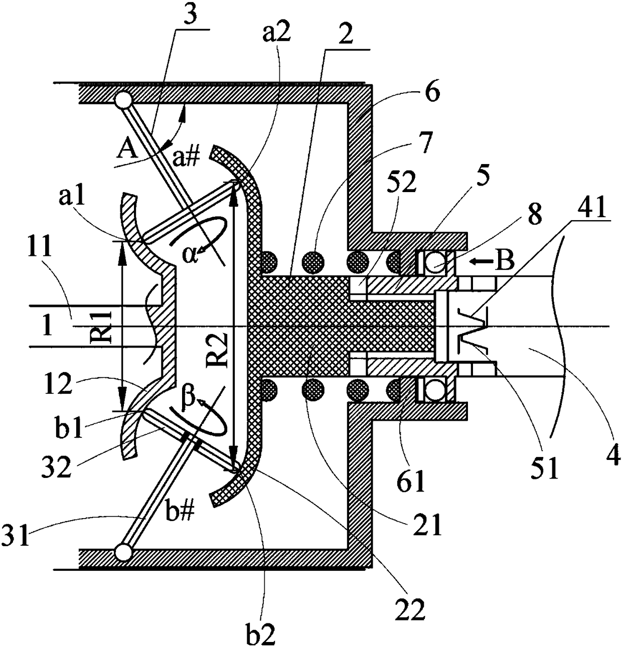
[0027] A transmission device capable of automatic speed regulation, including a driving shaft 1, a driven shaft 2, a transmission wheel 3 and a bracket 6, such as figure 1 As shown, the specific structure is:

[0028] The central axes of the drive shaft 1 and the driven shaft 2 coincide with each other; the drive shaft 1 includes a drive shaft body 11 and a drive transmission surface 12, and the front end of the drive shaft body 11 is vertically fixed at the center of the drive transmission surface 12, and the drive shaft The central axes of the body 11 and the driving transmission surface 12 coincide with each other; the driven shaft 2 includes a driven shaft body 21 and a driven transmission surface 22, and the rear end of the driven shaft body 21 is vertically fixed on the bottom of the driven transmission surface 22. At the center, the central axes of the driven shaft body 21 and the driven transmission surface 22 coincide with each other; the driving transmission surface ...

Embodiment 2

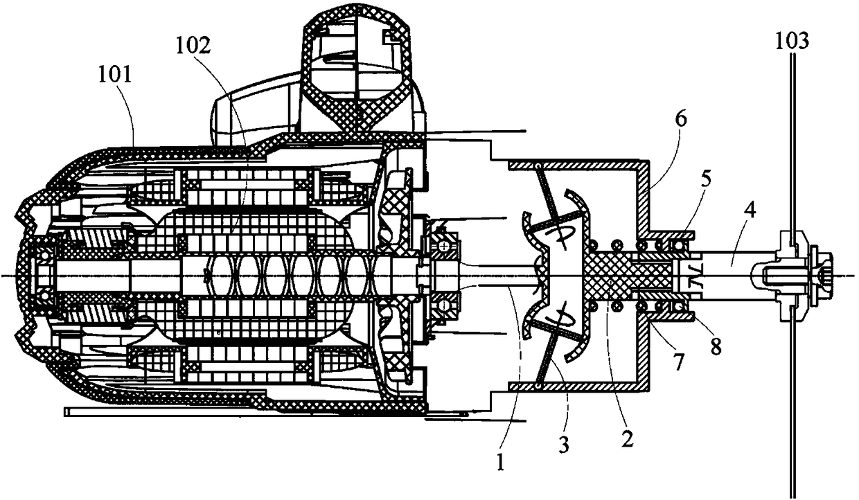
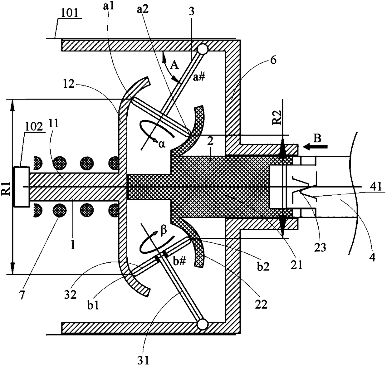
[0040] A transmission device capable of automatic speed regulation, including a driving shaft 1, a driven shaft 2, a transmission wheel 3 and a bracket 6, such as image 3 Shown, concrete structure and embodiment 1 are the same.

[0041] This embodiment is applied to electric tools, and the electric tools are cutting machines as an example, and can also be used for electric tools such as electric drills, grinders or electric saws, such as image 3 As shown: the electric tool includes a housing 101 and a power system 102 fixed in the housing 101; The connecting surface 41 matched with each other, the front end of the driven shaft 2 engages with the connecting surface 41 through the occlusal surface 23 to connect the output shaft 4; end against the driving transmission surface 12 and the power system 102 respectively; the bracket 6 is located in the housing 101 and can move in the housing 101, the power system 102 outputs torque through the drive shaft 1, and the front end of t...


PUM


Abstract

The invention relates to the field of transmission devices mainly comprising teeth or friction pieces, connecting rods or levers and cams or at least comprising two elements in the three types, in particular to a transmission device capable of automatically adjusting speed and an application method thereof. The transmission device capable of automatically adjusting speed comprises a driving shaft (1) and a driven shaft (2), and is characterized by further comprising a transmission wheel (3), an output shaft (4) and a bracket (6); a driving transmission surface (12) and a driven transmission surface (22) are oppositely arranged; the bracket (6) coats the driven shaft (2); at least one pair of transmission wheels (3) is arranged between the driving shaft (1) and the driven shaft (2); and the outer side surface of a transmission turntable (32) is respectively in rolling contact with the driving transmission surface (12) and the driven transmission surface (22). The application method of the transmission device capable of automatically adjusting speed is characterized by comprising transmission and adjustment. The transmission device capable of automatically adjusting speed is simple in structure, convenient for use, capable of automatically adjusting the speed and wide in application range.

Description

technical field [0001] The invention relates to the field of transmission mainly including teeth or friction parts, connecting rods or levers, cams, or at least two elements of these three types, specifically an automatic speed-adjustable transmission and its use method . Background technique [0002] The Chinese patent with the publication number 102056697A disclosed a "circular saw" on May 11, 2011, which includes a transmission mechanism of the prior art. The technical solution disclosed in the patent is that the speed change mechanism of the power tool has parallel The first and second rotating shafts and the first gear train and the second gear train having different transmission ratios are arranged, and the first gear train and the second gear train respectively have a gear for meshing with each other and for connecting the first rotating shaft. Torque is transmitted to the driving gear and the driven gear of the second rotating shaft, the torque transmission path thr...

Claims


Application Information

Patent Timeline
Patent Type & Authority Patents(China)
IPC IPC(8): F16H37/12
CPCF16H37/12
Inventor 徐江
Owner TONGJI UNIV
Why Eureka
Try Eureka