
Contour-parallel offset tool path linking method of double-ring-shaped sections

A connection method and cross-section technology, applied in the direction of instruments, digital control, control/regulation systems, etc., can solve problems such as non-compliant processing, achieve the effects of avoiding frequent tool jumps, smooth processing, and improving surface processing accuracy

Active Publication Date: 2016-08-10
ZHEJIANG UNIV
View PDF3 Cites 1 Cited by
  • Summary
  • Abstract
  • Description
  • Claims
  • Application Information

AI Technical Summary

Problems solved by technology

Secondly, the existing circular cutting tool rail connection methods often have the problem of repeated cutting or overcutting (such as the literature [HAO Yong-tao, JIANG Li-li. Optimal algorithm for no tool-retractions contour-parallel offset tool-path linking[J] .Chinese Journal of Mechanical Engineering,2007,20(2):21-25] and [Yang Feng, Liao Wenhe, Dai Ning, et al. Algorithm for transition connection of tool rail ring with no jumping tool point and vertical line[J]. China Mechanical Engineering , 2013, 24(19): 2592-2596]), did not follow the principle of starting from the CCW inner ring (such as the literature [DAI N, DONG G L, LIAO W H, et al.Dental restoration contour-paralleloffset tool path links based on graph model[J].The International Journal of Advanced Manufacturing Technology,2013,66(1-4):555-563])
Furthermore, existing methods need to establish a complex tool path ring relationship tree, which involves complex tree structure traversal problems (such as literature [PARK S C, CHUNG Y C, CHOIB K. Contour-parallel offset machining without tool-retractions [J] Computer -Aided Design, 2003, 35(9):841-849])

Method used

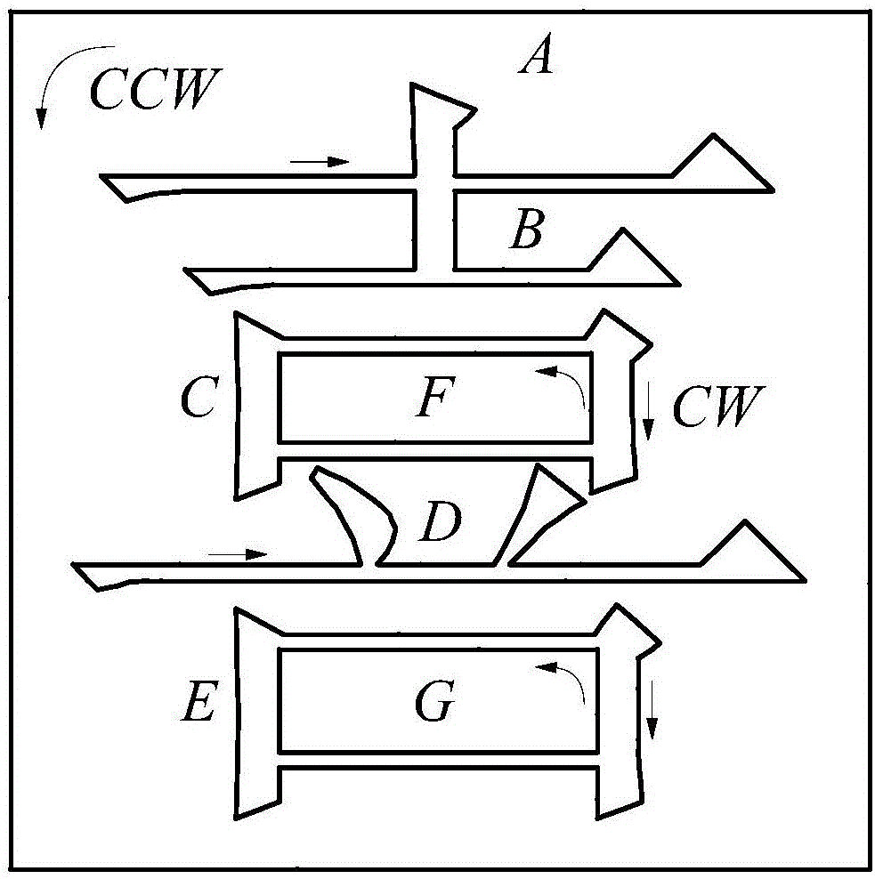
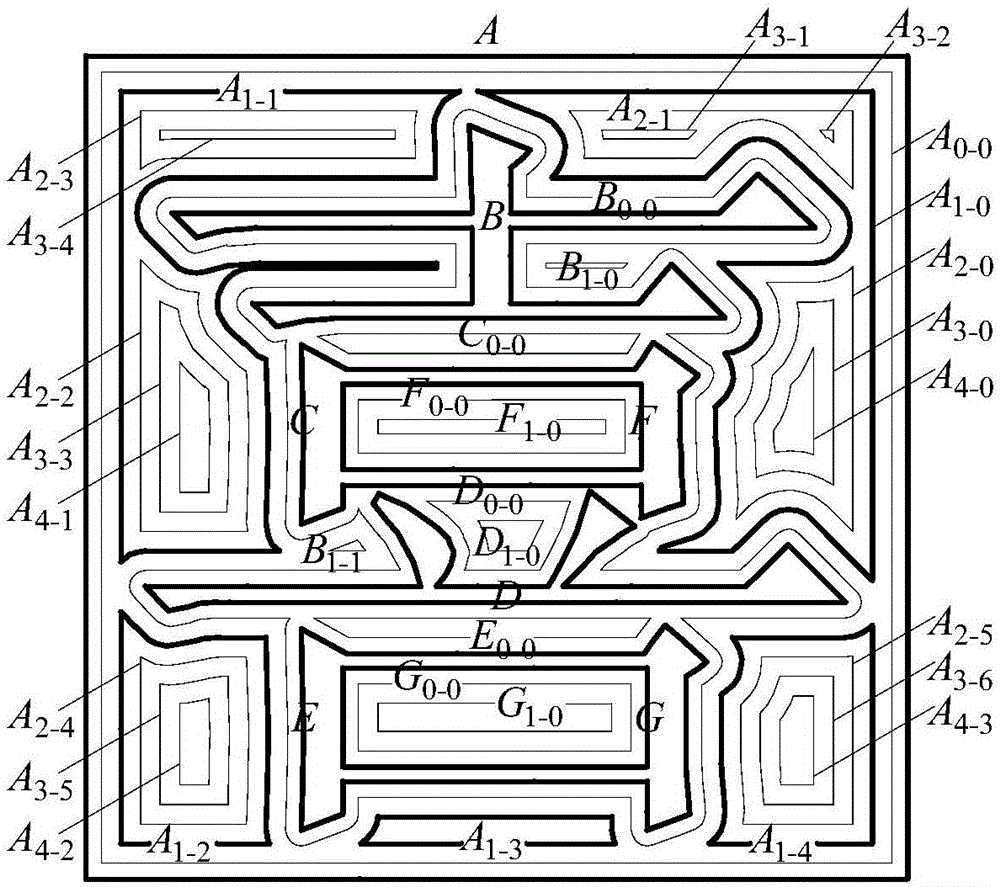
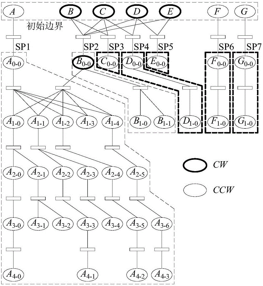

Image

  • Contour-parallel offset tool path linking method of double-ring-shaped sections
  • Contour-parallel offset tool path linking method of double-ring-shaped sections
  • Contour-parallel offset tool path linking method of double-ring-shaped sections

Examples


Embodiment 2

[0078] Figure 7 Given the case with multiple CW loops, p 1 is the starting point of processing, starting from p 1 ~p 8 Complete the machining of the CCW I-ring, as shown by the thin solid line in the figure. Since there is no CCW II-type ring, the next step is to start processing the CW-type ring, that is, the dotted line in the figure, and the processing route is p 8 ~p 15 , the thick dotted line in the figure is the jump route for lifting the knife. It can be seen from the figure that the CCW ring is processed from the inside to the outside, while the CW ring is processed from the outside to the inside, and the direction along the ring is also different.

Embodiment 3

[0080] Figure 8 Given the case where two CW parent rings are contained by the same CW child ring, p 1 is the starting point of processing, starting from p 1 ~p 12 Complete the machining of the CCW I-ring, as shown by the thin solid line in the figure. Since there is no CCW II-type ring, the next step is to process the CW-type ring, that is, the dotted line in the figure, first from p 12 point jump knife to p 13 point, slowly cut into p 14 point, then machine clockwise around the ring, back to p 14 After point, cut into p 15 point, process p clockwise 15 Point the ring, return to p 15 After point, cut into p 16 point, process p clockwise 16 Point the ring, return to p 16 After pointing, jump knife to p 17 point, process p clockwise 17 Point the ring, return to p 17 After point, cut into p 18 point, process p clockwise 18 Point the ring, return to p 18 After point, cut into p 19 point, process p clockwise 19 Point the ring, return to p...


PUM


Abstract

The invention discloses a contour-parallel offset tool path linking method of double-ring-shaped sections. Offset rings are divided into CW (clockwise) type offset rings, CCW (counter clockwise) I type offset rings and CCW (counter clockwise) II type offset rings; these three kinds of offset rings are searched based on inclusion relations, so that longest main links and a plurality of branch links are obtained; intersecting points are recorded, transitional connection points on the offset rings are solved one link by one link; a tool cuts in from the main link of the CCW I type offset rings, and performs counter clockwise machining from inner layers to outer edges; when meeting CCW I type local branch links, the tool firstly cuts into the innermost layer of the branch links and performs machining from inside to outside; the main link and branch links of the CCW II type offset rings are machined in a tool-retraction manner; and the main link and branch links of the CW type offset rings are machined in a tool-retraction manner along the clockwise direction of the rings from outer layers to inner layers. According to the method of the invention, the intersecting points of the branch links and main link are recorded repeatedly, and time when the main link and the branch links are connected together can be determined correspondingly. With the method adopted, the defect of frequent tool retraction in traditional line cutting machining can be effectively avoided, and a machining process more tends to be stable, and surface machining accuracy can be improved.

Description

technical field [0001] The invention relates to a method for processing geometric figures, in particular to a method for connecting ring-cut knife rails with a lake-shaped section in an island, and belongs to the application field of numerical control processing. Background technique [0002] The circular cutting tool track matches the contour of the workpiece to be processed, which can better ensure the machining accuracy of the contour, reduce the lifting of the tool and prolong the service life of the tool. Compared with the traditional line cutting method, it has great advantages. However, the generation of ring cutting tool path is more complicated, involving two major problems of offset ring generation and connection. Existing research mainly focuses on the situation that there are multiple "islands" in the figure, and there are relatively few studies on the "island with lake" cross-section, and this kind of problem is just relatively common, such as various stamps, fo...

Claims


Application Information

Patent Timeline
IPC IPC(8): G05B19/19
CPCG05B19/19G05B2219/35322
Inventor 何雪军王进陆国栋陈立金晶
Owner ZHEJIANG UNIV
Learn More