Rotary self-locking drum pad device
A self-locking, installation through-hole technology, applied to percussion instruments, musical instruments, instruments, etc., can solve the problems of time-consuming installation and inconvenient installation and operation, and achieve the effect of saving material cost, easy adjustment, and saving installation cost
- Summary
- Abstract
- Description
- Claims
- Application Information
AI Technical Summary
Problems solved by technology
Method used
Image
Examples
Embodiment 1
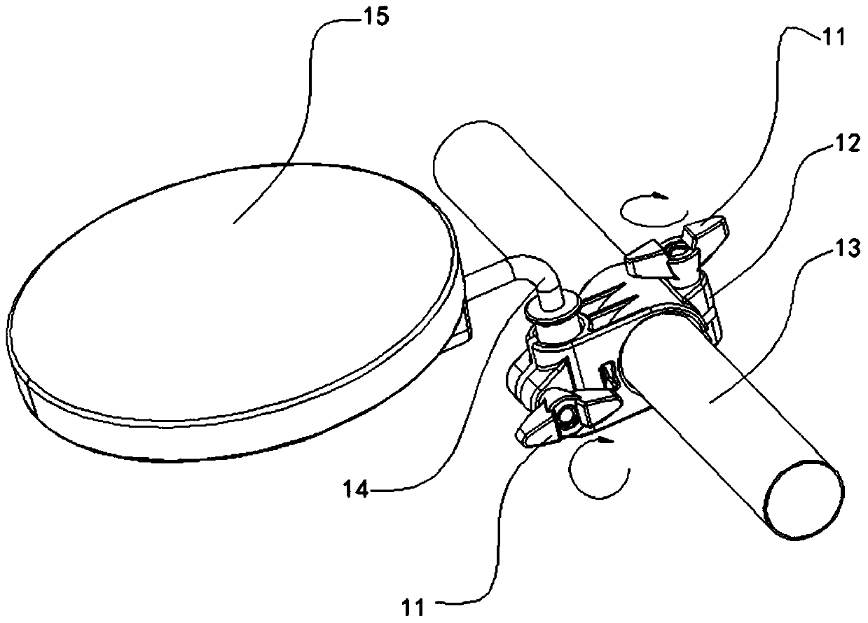
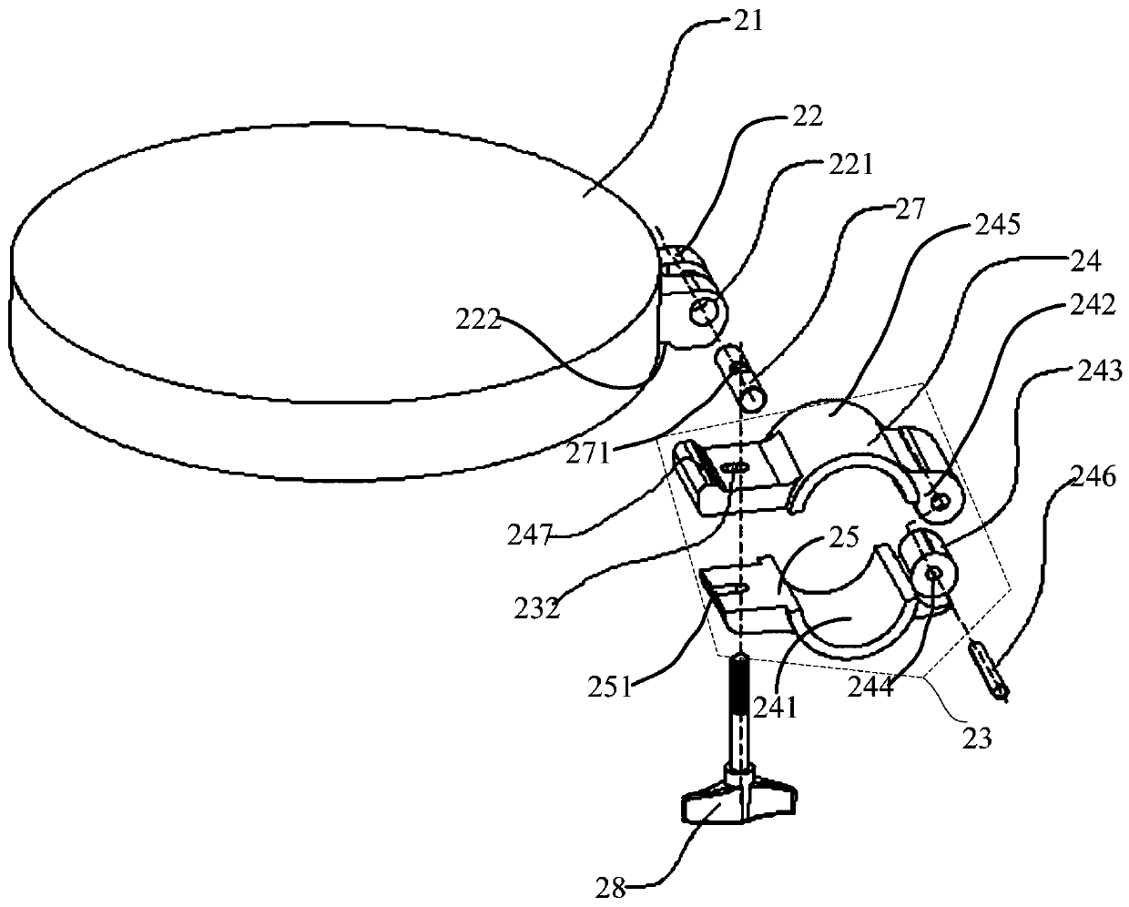
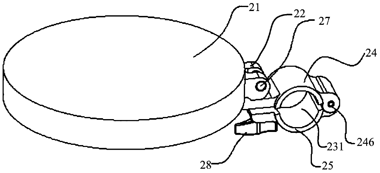
[0072] see Figure 2 to Figure 4 , the present invention provides a rotary self-locking drum pad beating device, the rotary self-locking drum pad device includes: a drum pad 21, a pair of drum pad pin fixing structures 22 are provided on the side of the drum pad 21, the drum pad The pad pin fixing structure 22 is provided with a corresponding drum pad pin shaft hole 221; the main body 23, the inside of the main body 23 is provided with a first installation through hole 231, and the main body 23 is provided with a second installation through hole 232 near one end. a connection assembly, the connection assembly is adapted to connect the drum pad 21 with the main body 23 through the second installation through hole 232 and the drum pad pin hole 221 .
[0073] As an example, the main body 23 includes an upper cover 24 and a lower cover 25, the upper cover 24 and the lower cover 25 both include a first end and a second end, the first end of the upper cover 24 and the lower cover 25...
Embodiment 2
[0102] see Figure 11 , the present invention also provides a rotary self-locking drum pad device. The structure of the rotary self-locking drum pad device in this embodiment is substantially the same as that of the rotary self-locking drum pad device described in Embodiment 1. The difference lies in the structure of the main body 23 .
[0103] As an example, the main body 23 includes a housing 26 and a lug structure 261; the first installation through hole 231 is located in the housing 26; The opening 262, the length direction of the opening 262 is along the axial direction of the first installation through hole 231; the lug structure 261 is respectively fixed on the surface of the housing 26 on both sides of the opening 262; Two installation through holes 232 are correspondingly disposed in the lug structure 261 .
[0104] As an example, a locking mechanism is provided on the outer side of the lug structure 261 away from the housing 26 and below the joint between the drum ...
PUM
 Abstract
Description
Claims
Application Information
 - R&D
- Intellectual Property
- Life Sciences
- Materials
- Tech Scout
- Unparalleled Data Quality
- Higher Quality Content
- 60% Fewer Hallucinations
Browse by: Latest US Patents, China's latest patents, Technical Efficacy Thesaurus, Application Domain, Technology Topic, Popular Technical Reports.
© 2025 PatSnap. All rights reserved.Legal|Privacy policy|Modern Slavery Act Transparency Statement|Sitemap|About US| Contact US: help@patsnap.com


