
Transformers and switching power supply units

A technology of switching power supply and transformer, which is applied in the parts of transformer/inductor, transformer/inductor coil/winding/connection, circuit, etc. It can solve the problems of deviation and different coupling coefficients, and achieve the effect of suppressing deviation

Active Publication Date: 2020-04-03
TAMURA KK
View PDF5 Cites 0 Cited by
  • Summary
  • Abstract
  • Description
  • Claims
  • Application Information

AI Technical Summary

Problems solved by technology

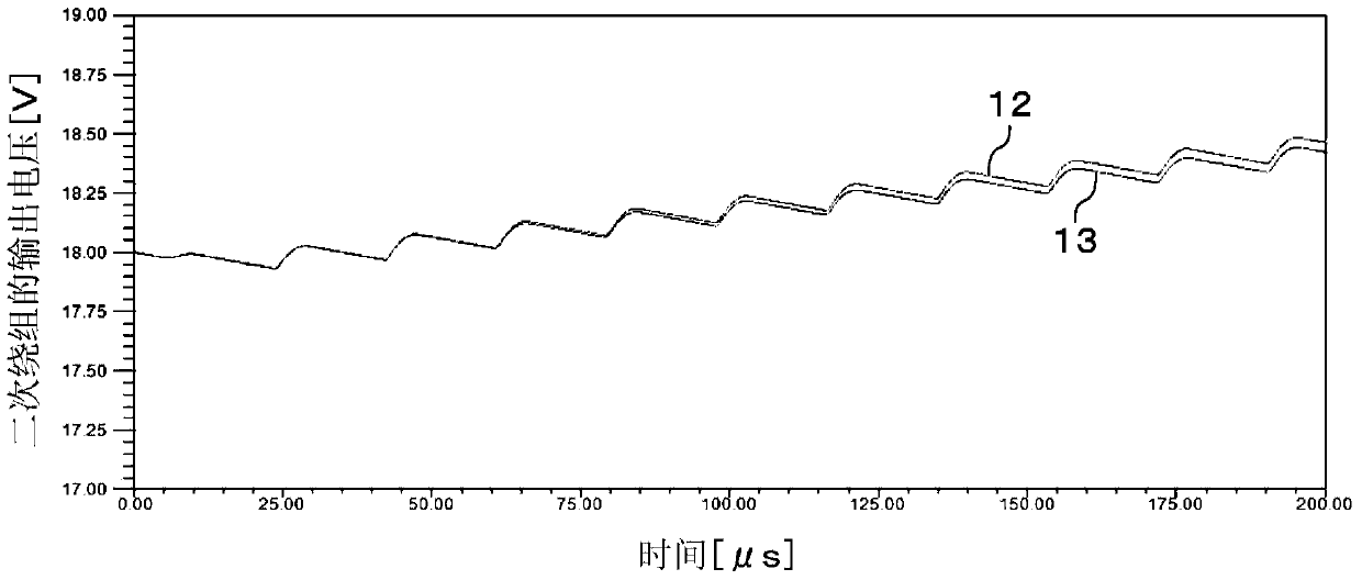
Therefore, even if the output voltages from the secondary windings 112 and 113 are intended to be the same, there is a problem that deviation occurs.
[0006] and, if Figure 16 As shown, even if the secondary windings 112, 113 are arranged equidistant from the air gap 115, when the distances from the primary winding 111 are different, the coupling coefficients to the primary winding 111 are different. Even if the output voltages of the secondary windings 112 and 113 are the same, the problem of deviation will also occur

Method used


Image

  • Transformers and switching power supply units
  • Transformers and switching power supply units
  • Transformers and switching power supply units

Examples


no. 2 Embodiment approach

[0055] [2-1. Structure]

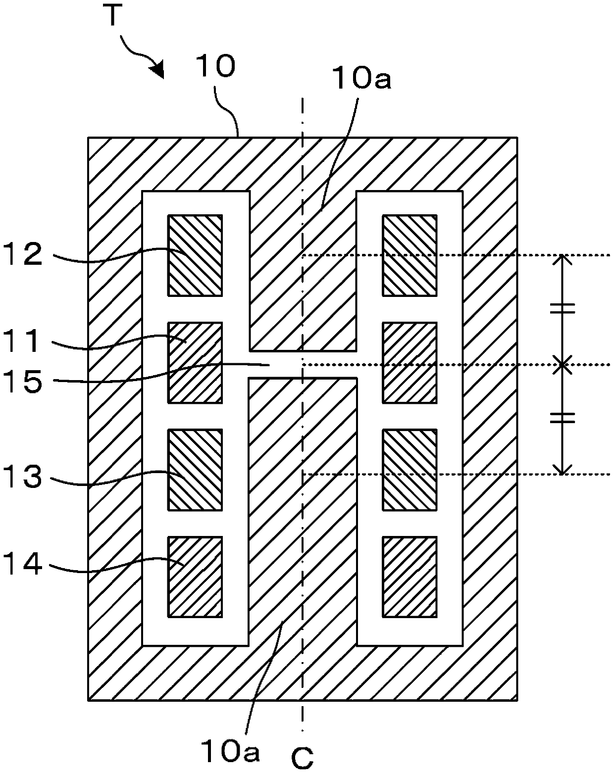
[0056] use Figure 4 ~ Figure 11 A second embodiment will be described. The basic configuration of the second embodiment is the same as that of the first embodiment. Therefore, only the differences from the first embodiment will be described, and the same reference numerals will be assigned to the same parts as in the first embodiment, and detailed description will be omitted.

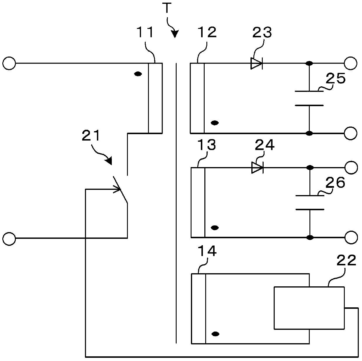
[0057] Figure 4 It is a schematic sectional view showing the overall structure of the transformer of the second embodiment. Figure 5 It is a circuit diagram of a switching power supply device using the transformer T of the second embodiment. The difference from the first embodiment is that two or more (here, two) auxiliary windings 14 and 16 are provided.

[0058] That is, the difference lies in that the auxiliary windings 14 and 16 are respectively provided adjacent to the secondary windings 12 and 13 in the winding axis direction of the respective windings 11 to 13 an...


PUM


Abstract

The invention provides a transformer and a power source switching device. The transformer can suppress deviation of each output voltage. The power source switching device uses the transformer. The transformer (T) includes: a magnetic core (10); a primary winding (11) which is arranged on the magnetic core (10); an air gap (15) which is arranged on a part providing with the primary winding, of the magnetic core (10); and more than two secondary windings (12, 13) which are arranged on the magnetic core (10), are arranged at two sides of the primary winding (11) in the reel shaft direction of the primary winding (11), and have the same distances from the air gap (15). The power source switching device includes the transformer (T), a switching element connected to the primary winding (11) of the transformer (T), and a control circuit for controlling the switching element.

Description

technical field [0001] The present invention relates to a transformer and a switching power supply device using the transformer, in particular to the structure of the transformer. Background technique [0002] In order to operate electric equipment and circuits, a stable DC voltage is required, and a switching power supply device has conventionally been used to generate this DC voltage. A switching power supply device rectifies and smoothes the voltage supplied from an external power supply, performs switching operations through a semiconductor switching element, inputs it to the primary winding of a transformer, and supplies a DC voltage from the secondary winding of the transformer to the load through smoothing by a smoothing circuit. Then, the output voltage is monitored, and the timing of the semiconductor switching element is adjusted by the control circuit so that the output voltage is kept constant. [0003] Among such switching power supply devices, conventionally k...

Claims


Application Information

Patent Timeline
Patent Type & Authority Patents(China)
IPC IPC(8): H02M3/28H01F27/30H01F3/14
CPCH01F3/14H01F27/306H02M3/28
Inventor 小川纮生
Owner TAMURA KK
Learn More