
Recording apparatus

Active Publication Date: 2015-05-21
SEIKO EPSON CORP
View PDF1 Cites 0 Cited by
  • Summary
  • Abstract
  • Description
  • Claims
  • Application Information

AI Technical Summary

Benefits of technology

The present invention is about a recording apparatus that includes a transport drum that supports and transfers a recording medium, and a drying unit that dries ink recorded on the medium. The advantage of this invention is that it uses the inside of the transport drum effectively, and the drying unit is included inside. This makes it possible to use the space inside the transport drum. Additionally, the invention includes a mechanism that prevents vibration from the rotating drum from affecting the recording medium, and ensures efficient drying of the ink by releasing steam generated from the ink. The invention also reduces friction between the recording medium and the outer surface of the transport drum, which makes it easy to transport and suppresses deviation of the medium.

Problems solved by technology

However, as disclosed in JP-A-10-86472, in the recording apparatus of the related art including the transport drum that supports and transports the recording medium on the outer peripheral surface thereof, it cannot be said that the inside of the transport drum has been effectively used.
However, the recording apparatus including the transport drum that supports and transports the roll-shaped recording medium on the outer peripheral surface in the related art, is not configured to have a configuration in which the transport drum can be rotated multiple times and thus the image can be recorded by dividing the image into multiple images.

Method used


Image

  • Recording apparatus
  • Recording apparatus
  • Recording apparatus

Examples


example 1

, FIGS. 1 to 3

[0034]Hereinafter, a recording apparatus 1 according to an Example 1 of the present invention will be described in detail with reference to the accompanying drawings.

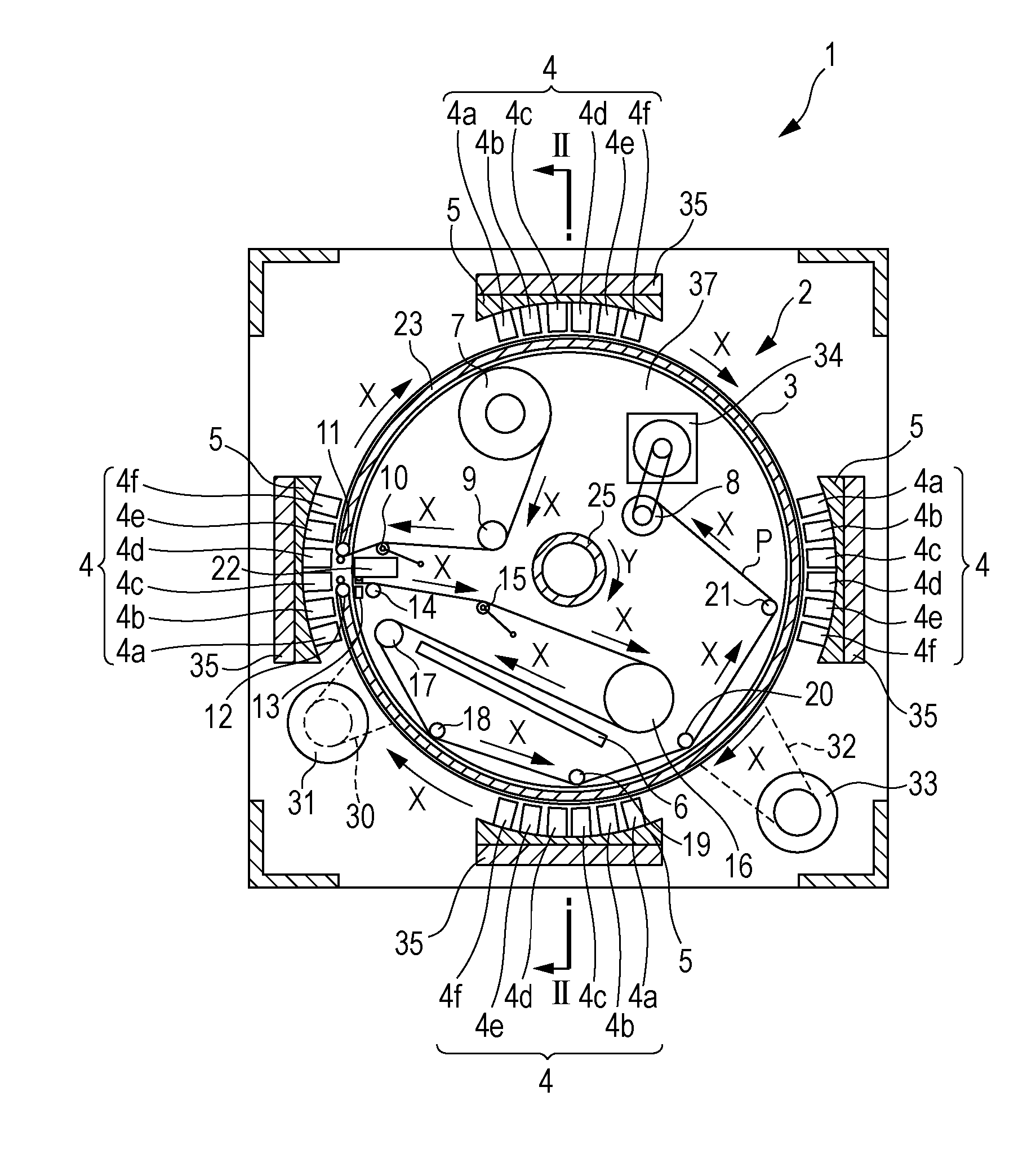
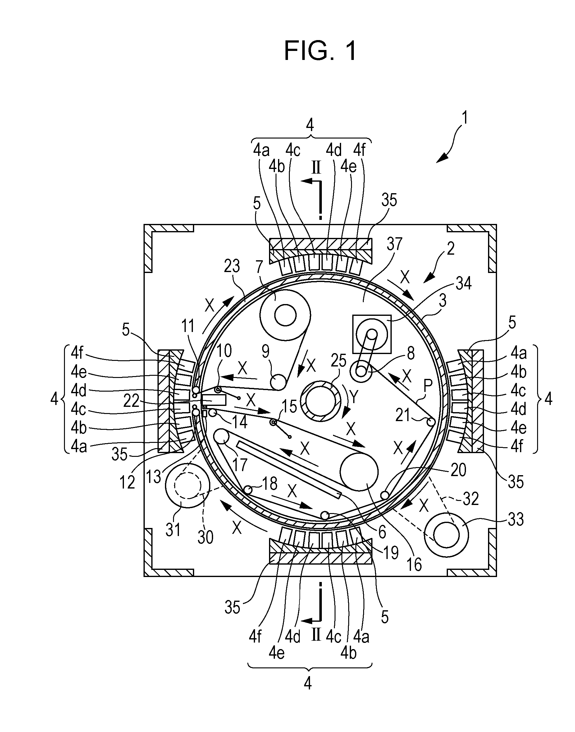
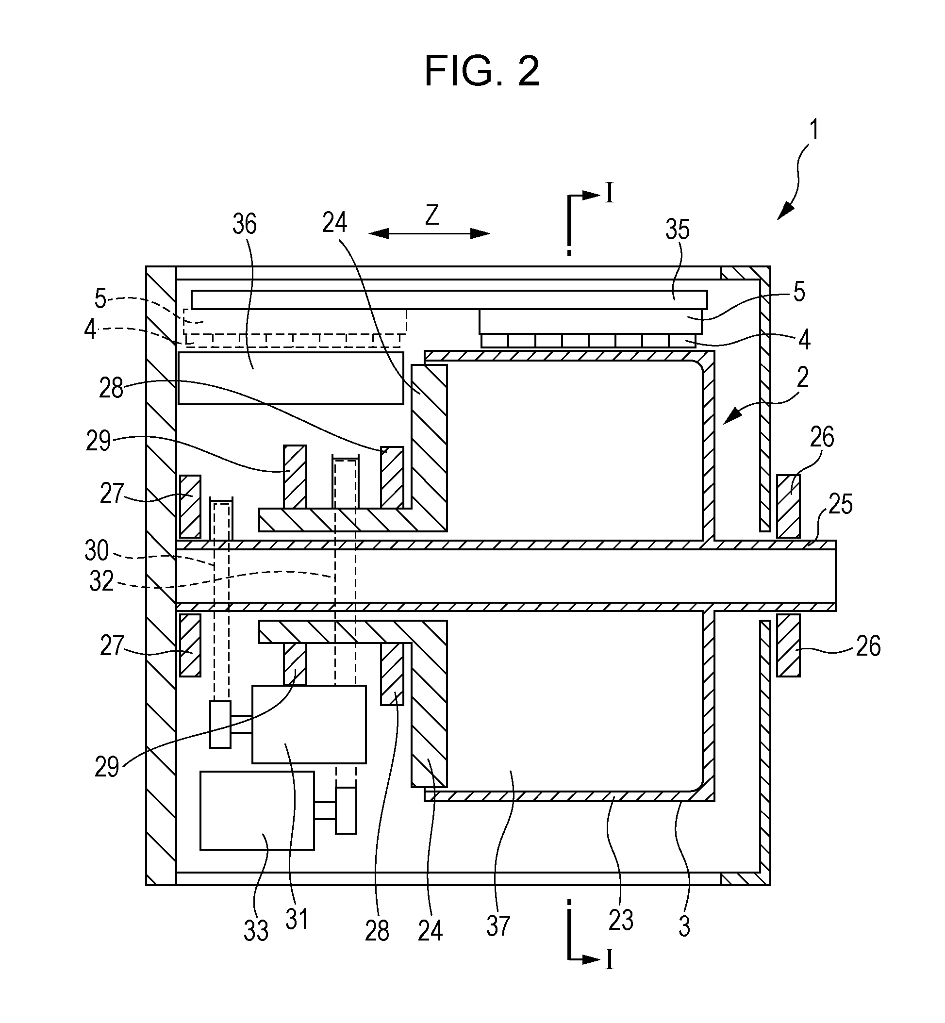
[0035]FIG. 1 is a schematic planar sectional view illustrating a recording apparatus 1 according to Example 1 of the invention. In addition, FIG. 2 is a schematic side sectional view illustrating the recording apparatus 1 according to Example 1 of the invention.

[0036]FIG. 2 is a cross-sectional view taken along dotted line II-II of FIG. 1, and FIG. 1 is a cross-sectional view taken along dotted line I-I of FIG. 2. In FIG. 2, in order to make a description of the recording apparatus 1 to be easily understood, the recording medium P and a configuration member of the inside 37 of the transport drum 2 are omitted.

[0037]In the recording apparatus 1 according to the example of the invention, the transport drum 2 that supports and transports the recording medium P on the outer peripheral surface 3 is included. In...

example 2

, FIG. 4

[0074]Next, a recording apparatus according to Example 2 will be described in detail with reference to the accompanying drawings.

[0075]FIG. 4 is a schematic plan view illustrating a transport drum 2 according to the Example 2. In addition, like numbers reference like components which are the same as the above example, and the detailed description thereof will be omitted.

[0076]A recording apparatus 1 according to the example of the invention is configured to have the same configuration as the recording apparatus 1 of the Example 1 except for the configuration in which a cover 40 is provided with a hole 39 to upper portion of the transport drum 2, instead of the cover 38 which is attached to blind the inside 37 of the transport drum 2.

[0077]In addition, as illustrated in FIG. 4, in the cover 40 on the upper portion of the transport drum 2 according to the example of the invention, the hole 39 is provided so as to open on a part thereof to the outside. For this reason, steam of...


PUM


Abstract

A recording apparatus includes a transport drum that supports and transports a recording medium on an outer peripheral surface thereof, a recording head that is provided in a position so as to be capable of facing the outer peripheral surface and ejects ink onto the recording medium, and a drying unit that is provided in the inside of the transport drum and dries the ink.

Description

BACKGROUND[0001]1. Technical Field[0002]The present invention relates to a recording apparatus including a transport drum that supports and transports a roll-shaped recording medium on an outer peripheral surface thereof.[0003]2. Related Art[0004]In the related art, a recording apparatus including a drying unit that dries a transport drum supporting and transporting a recording medium on an outer peripheral surface thereof has been used. Among these, for example, as recording apparatuses disclosed in JP-A-10-86472, JP-A-2003-94615, and JP-A-2009-227466, a recording apparatus including a transport drum that supports and transports a roll-shaped recording medium on an outer peripheral surface thereof has been used.[0005]On the other hand, since the recording speed of a recent recording apparatus has become fast, a recording apparatus including a drying unit has been used so as to promote drying of ink ejected from a recording head onto a recording medium.[0006]A recording apparatus in...

Claims


Application Information

Patent Timeline
IPC IPC(8): B41J11/00
CPCB41J11/002B41J11/04B41J15/02B41J11/00216B41J11/0022
Inventor MATSUHASHI, KUNIHIKO
Owner SEIKO EPSON CORP
Learn More