Cushioned pallet assembly

Inactive Publication Date: 2010-08-26
LIN DANIEL
View PDF12 Cites 23 Cited by
  • Summary
  • Abstract
  • Description
  • Claims
  • Application Information

AI Technical Summary

Benefits of technology

[0007]Therefore, the object of the present invention is to prov

Problems solved by technology

Because there is high friction between the loaded pallet and the ground, it is not possible for a worker to push and move the pallet on the ground, so

Method used


Image

  • Cushioned pallet assembly
  • Cushioned pallet assembly
  • Cushioned pallet assembly

Examples


Example

[0020]Before the present invention is described in greater detail, it should be noted that the same reference numerals have been used to denote like elements throughout the specification.

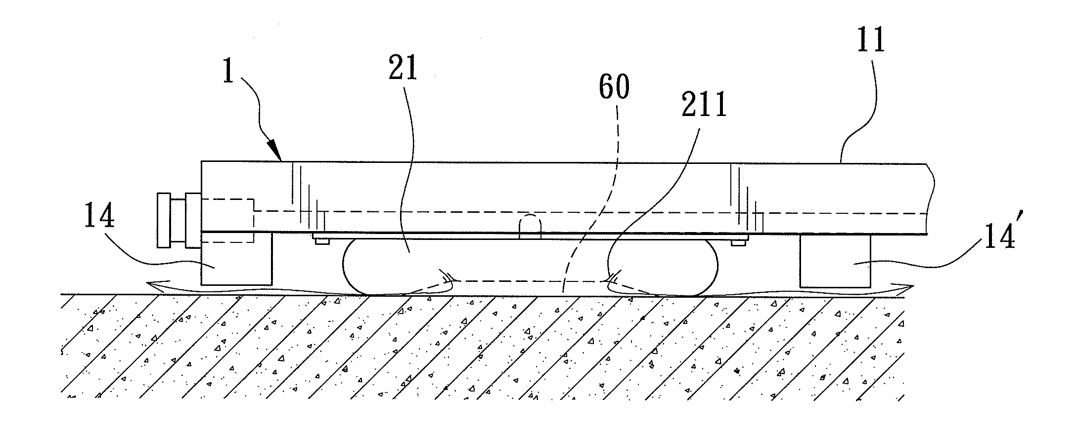
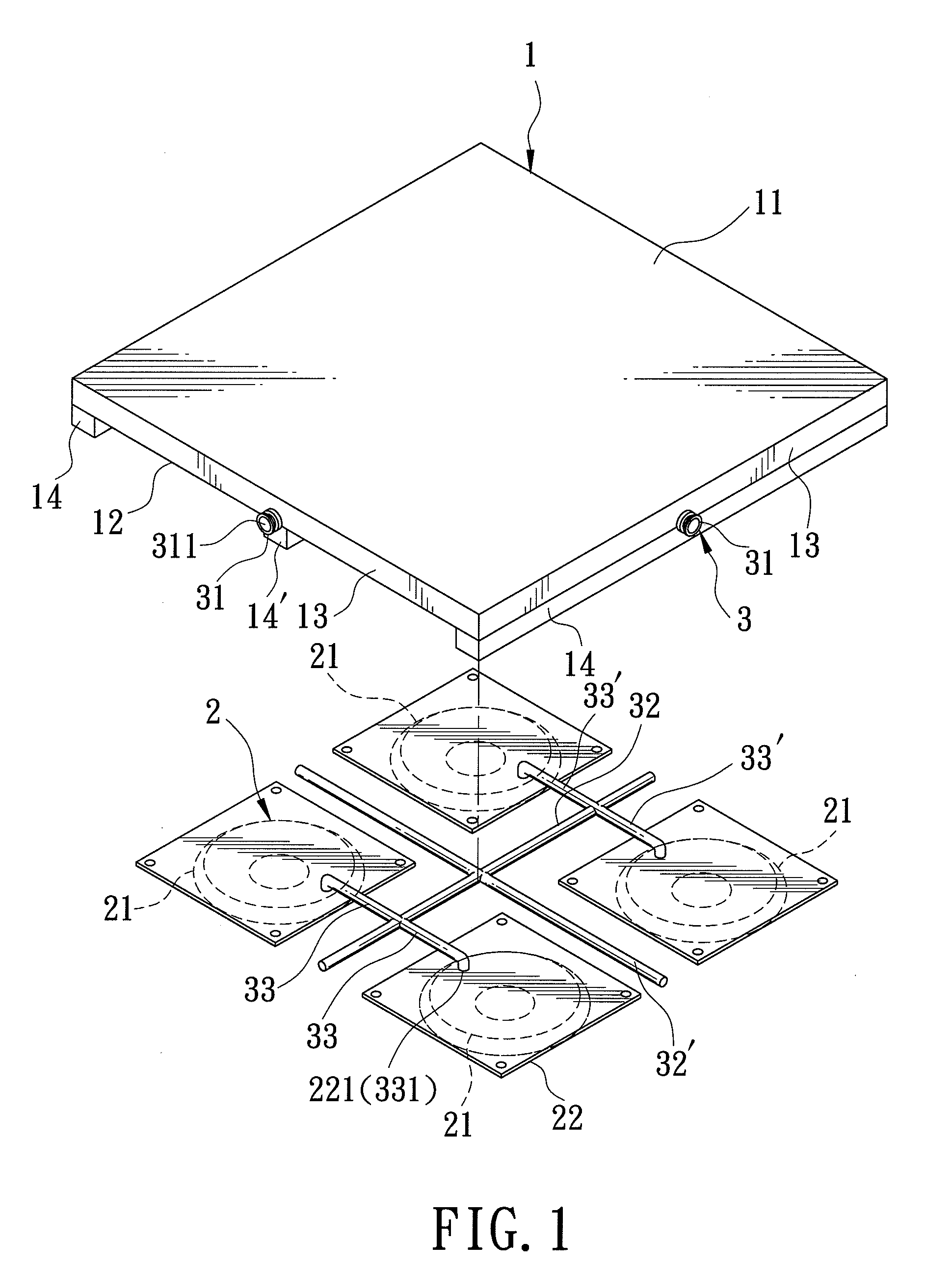
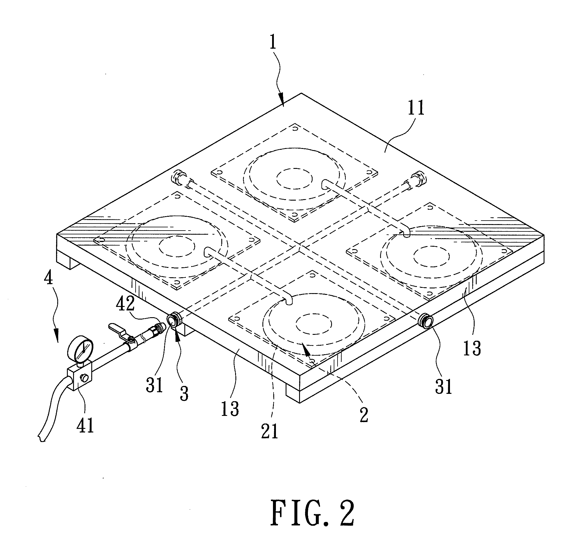
[0021]Referring to FIGS. 1 to 5, a cushioned pallet assembly according to the first preferred embodiment of the present invention is shown to comprise a rigid pallet body 1, an air bag unit 2, and an air supply conduit unit 3.

[0022]The rigid pallet body 1 has a top face 11 adapted to hold a load, a bottom face 12, four lateral sides 13 interconnecting lateral ends of the top and bottom faces 11, 12, and three parallel and spaced-apart standoff bars 14, 14′ disposed beneath the bottom face 12. Two of the standoff bars 14 extend along two of the lateral sides 13. The standoff bar 14′ is disposed between the standoff bars 14. In this embodiment, the pallet body 1 has a size conforming to international standards, and is thus suitable for use in Taiwan and other countries.

[0023]The air bag unit 2 include...


PUM


Abstract

A cushioned pallet assembly includes a rigid pallet body having four lateral sides, an air bag unit including at least one inflatable air bag mounted to the pallet body and capable of producing a pressurized layer of air beneath the air bag, and an air supply conduit unit connected to the air bag for supplying air to the same. The pallet body further has top and bottom faces. The air bag is disposed below the bottom face of the pallet body.

Description

CROSS-REFERENCE TO RELATED APPLICATION[0001]This application claims priority of Taiwanese Application No. 098105640, filed on Feb. 23, 2009.BACKGROUND OF THE INVENTION[0002]1. Field of the Invention[0003]This invention relates to a pallet, more particularly to a cushioned pallet assembly.[0004]2. Description of the Related Art[0005]Conventionally, a hydraulic hand jack or a forklift may be used to move a pallet from one place to another. Because there is high friction between the loaded pallet and the ground, it is not possible for a worker to push and move the pallet on the ground, so that use of a hydraulic hand jack or forklift is necessary to raise the pallet from the ground and then move the same to a desired place or position.[0006]Although the aforesaid two types of transport machines can be used to move a pallet, use of these transport machines makes it necessary to assess accurately the number of transport machines and the number of skilled workers required prior to a trans...

Claims


Application Information

Patent Timeline
IPC IPC(8): B60V1/00B65D19/02B65D19/38
CPCB60V3/025B65D19/0026B65D19/40B65D2519/00273B65D2519/00786B65D2519/00323B65D2519/00333B65D2519/00781B65D2519/00288
Inventor LIN, DANIEL
Owner LIN DANIEL
Why Eureka
Try Eureka