Liquid ejection head and recording apparatus

Active Publication Date: 2019-10-10
CANON KK
View PDF0 Cites 0 Cited by
  • Summary
  • Abstract
  • Description
  • Claims
  • Application Information

AI Technical Summary

Benefits of technology

The present invention is about a liquid ejection head that can prevent problems like poor ink placement when air flows in, while also allowing for faster recording.

Problems solved by technology

It is difficult of suppress such an influence exerted by the inflowing airflow with the method described in Japanese Patent No. 3907685.

Method used


Image

  • Liquid ejection head and recording apparatus
  • Liquid ejection head and recording apparatus
  • Liquid ejection head and recording apparatus

Examples


first example embodiment

Description of Recording Apparatus

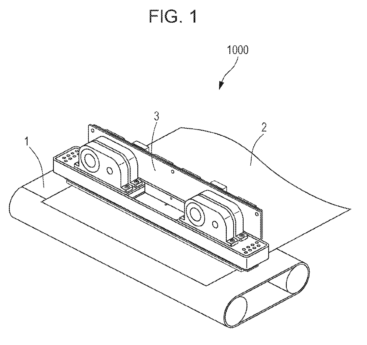
[0022]Referring to FIG. 1, a configuration of a recording apparatus according to a first example embodiment will be described. FIG. 1 illustrates a recording apparatus 1000 equipped with a liquid ejection head 3, which ejects liquid, according to the present example embodiment. The recording apparatus 1000 includes a conveying unit 1 that conveys a printed medium 2 such as paper, and a page wide type liquid ejection head 3 disposed substantially orthogonal to a conveyance direction of the printed medium 2. The recording apparatus 1000 is a page wide type recording apparatus that performs continuous recording in one pass while conveying the printed medium 2 continuously or intermittently.

[0023]Furthermore, other than the above, the recording apparatus 1000 includes an ink tank (not shown) that contains ink, a liquid supply passage (not shown) that supplies the ink from the ink tank to the liquid ejection head 3, an electric control unit (not shown) t...

second example embodiment

[0049](A Case in which there are More than Three Ejection Opening Rows)

[0050]In the example embodiment described above, for the purpose of description, the recording element substrates in which three ejection opening rows are arranged are used. However, in order to perform one-pass printing with the page wide type head in a more effective manner, it is desirable that the number of ejection opening rows is larger than three. The present disclosure can be applied in a similar manner even in a recording element substrate in which more than three ejection opening rows are arranged. Description will be given below with reference to FIG. 7.

[0051]FIG. 7 illustrates a simulation result showing the amounts of deviation in the landing positions of an ejection openings group at the end portion of each ejection opening rows in a recording element substrate in which 32 ejection opening rows were arranged side by side in the relative movement direction. The axis of abscissas indicates the number ...

third example embodiment

[0054](A Case in which there are Ejection Opening Rows that are not Used)

[0055]In the recording element substrate 10 in which a plurality of ejection opening rows are arranged, there are cases in which, in consideration of the durability life of the recording element substrate, spare rows that are not used initially in the recording are provided or the rows are used alternately to elongate the product life of the liquid ejection head. The influence of the airflow on the recording can only be exerted between the rows being used (performing ejection and recording). In such a case, the rows that are used may be taken into consideration and the present disclosure can be applied to the rows that are used. Description of the present example embodiment will be given with reference to FIGS. 8A and 8B.

[0056]In the recording element substrate 10 in FIGS. 8A and 8B, among the entire eight ejection opening rows, for example, four recording ejection opening rows (17a, 17c, 17e, and 17g) illustra...


PUM


Abstract

A liquid ejection head including recording element substrates each including ejection opening rows in which ejection openings ejecting liquid are arranged, the plurality of ejection opening rows being juxtaposed in a relative movement direction with respect to the printed medium. In the relative movement direction of the printed medium when the printed medium is viewed from the liquid ejection head, and in the plurality of ejection opening rows provided in the recording element substrate, among the plurality of recording element substrates, positioned on an upstream side in the relative movement direction, arrangement intervals of ejection openings in an end area of an ejection opening row positioned on a most upstream side in the relative movement direction are smaller than arrangement intervals of ejection openings in an end area of an ejection opening row positioned on a most downstream side in the relative movement direction.

Description

BACKGROUND OF THE DISCLOSUREField of the Disclosure[0001]The present disclosure relates to a liquid ejection head and a recording apparatus that eject liquid such as ink on a printed medium to perform recording.Description of the Related Art[0002]Ink jet recording apparatuses which eject droplets with a liquid ejection head to perform recording are widely used. Until droplets ejected from ejection openings of a liquid ejection head land on a printed medium, the air having viscosity situated around the flying droplets is dragged by the movement of the droplets and is moved as well. With the above, an area between an ejection opening surface provided with the ejection openings and the printed medium tends to become lower in pressure than the surroundings thereof, and the surrounding air flows into the above pressure decreased area. It is known that as a result of the above, the droplets ejected particularly from ejection openings, among the ejection openings included in the ejection o...

Claims


Application Information

Patent Timeline
IPC IPC(8): B41J2/05B41J2/14B41J2/045
CPCB41J2/05B41J2/14B41J2/04501B41J2002/14475B41J2/155B41J2/1404B41J2202/20B41J2202/21
Inventor KOBAYASHI, MASAKAZUISHIDA, KOICHIIWANAGA, SHUZO
Owner CANON KK
Why Eureka
Try Eureka