Simulated cutting force loading device for three-axis boring mill and use method

A loading device and cutting force technology, which is applied in the testing of measuring devices, instruments, machines/structural components, etc., can solve the problems of expensive processing tools, large consumption of material objects and processing tools, and low test reliability, so as to reduce the The Effect of Machine Tool Performance Testing Costs

Active Publication Date: 2016-08-17
NORTHEASTERN UNIV LIAONING
View PDF6 Cites 6 Cited by
  • Summary
  • Abstract
  • Description
  • Claims
  • Application Information

AI Technical Summary

Problems solved by technology

[0004] At this stage, there are mainly two ways to realize machine tool performance testing. The first is to realize the actual processing of materials by the machine tool, and the second is to realize the machine tool processing process by computer simulation; the machine tool through the first method Performance testing requires the consumption of a large amount of material objects and processing tools, and the price of processing tools is very expensive. Often a performance test process requires several processing tools, and the above costs are included in the manufacturing cost of the machine tool, but this The machine tool performance test method is the most reliable, which can ensure that the machine tool has the best performance after leaving the factory. The disadvantage is that the manufacturing cost of the machine tool is high; the machine tool performance test through the second method, although the test cost is very low, but the test reliability It is also very low. The computer simulation is the ideal processing process, but the actual processing process is uncertain. Even if the performance test is completed in the computer simulation, the machine tool still cannot avoid failures in the actual processing process. occurs, although the manufacturing cost of the machine tool is reduced, and the performance of the machine tool is also sacrificed

Method used


Image

  • Simulated cutting force loading device for three-axis boring mill and use method
  • Simulated cutting force loading device for three-axis boring mill and use method
  • Simulated cutting force loading device for three-axis boring mill and use method

Examples


Embodiment Construction

[0024] The present invention will be further described in detail below in conjunction with the accompanying drawings and specific embodiments.

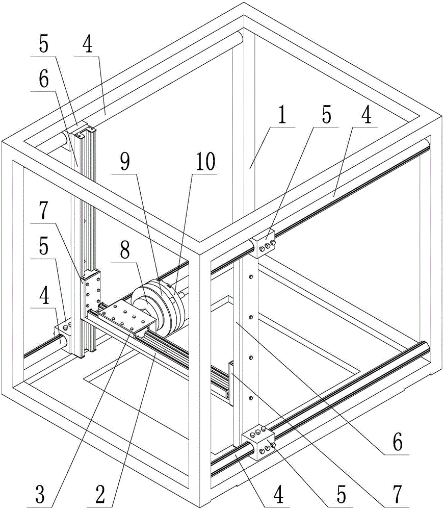
[0025] Such as Figure 1~4 As shown, a three-axis boring machine simulates a cutting force loading device, including a rigid frame 1, an X-direction position adjustment assembly, a Y-direction cutting force loading assembly, a Z-direction position adjustment assembly, and a tool turning steering cutting force loading assembly. The position adjustment assembly includes X-direction slide rail 2 and X-direction slide block 3, the Y-direction cutting force loading assembly includes Y-direction rail 4 and Y-direction slide block 5, and the Z-direction position adjustment assembly includes Z-direction slide rail 6 and The Z-direction slider 7, the tool turning steering cutting force loading assembly includes the tool turning steering plate 8, the tool turning turning disk 9 and the simulated flat rotating disk 10;

[0026] The Y-direction ...


PUM


Abstract

The invention provides a simulated cutting force loading device for a three-axis boring mill and a use method. The device comprises a rigid framework, an X-direction position adjustment assembly, a Y-direction cutting force loading assembly, an X-direction position adjustment assembly and a cutter rotation-direction cutting force loading assembly. The method comprises steps as follows: the simulated cutting force loading device is hoisted on a bench of a machine tool, the position of a simulating facing head is adjusted through the X-direction position adjustment assembly and the Y-direction position adjustment assembly and fixed, and a boring bar on the simulating facing head and a boring bar on the facing head of the machine tool are fixedly connected; a group of cutting force is set, pretightening bolts in the Y-direction cutting force loading assembly and the cutter rotation-direction cutting force loading assembly are tightened through a torque wrench, so that friction force in the cutting force loading assemblies is equal to the set cutting force, and friction force needs to be read out after the tightening torque is calculated according to the formula M=KFd / mu due to the fact that the friction force cannot be directly read; the machine tool is started and runs machining programs, the actual operation state of the machine tool is simulated really under the force bearing condition, and the performance of the machine tool under the current cutting force condition is tested.

Description

technical field [0001] The invention belongs to the technical field of machine tool performance testing, and in particular relates to a three-axis boring machine simulation cutting force loading device and a use method. Background technique [0002] At present, the three-axis boring machine is mainly used for boring the inner holes of parts. In many industries, the three-axis boring machine has become an indispensable processing equipment. Due to different machine tool manufacturers, the machine tool products of each machine tool manufacturer are often different in performance. Due to the differences in machine tool performance, the actual processing capabilities of machine tools are also significantly different. For machine tool purchasing enterprises, they all hope to be able to purchase machine tool products with better performance at a lower price, but the actual situation is that the price of machine tools is often linked to the performance of machine tools. The better ...

Claims


Application Information

Patent Timeline
Patent Type & Authority Applications(China)
IPC IPC(8): G01M99/00
CPCG01M99/005G01M99/007
Inventor 李常有张亚楠张义民黄贤振张旭方朱丽莎姚国吕昊吕航原谭学飞
Owner NORTHEASTERN UNIV LIAONING
Why Eureka
Try Eureka