
Analysis method of layered cutting difference between left and right cutting edge of tool

An analysis method and a difference technology, which is applied in the field of layered cutting difference analysis of the left and right cutting edges of the tool, and the difference analysis field when the tool is cutting, and can solve the problems of inability to carry out difference analysis, unstable turning process, poor thread surface consistency, etc. question

Inactive Publication Date: 2019-01-22
HARBIN UNIV OF SCI & TECH
View PDF3 Cites 0 Cited by
  • Summary
  • Abstract
  • Description
  • Claims
  • Application Information

AI Technical Summary

Problems solved by technology

[0005] The purpose of the present invention is to solve the problem that in the prior art, when the left and right blades of the tool cut large-pitch threads in layers, the difference analysis cannot be carried out during the cutting process of the left and right blades of the tool, resulting in unstable turning process and poor consistency of the cut thread surface

Method used


Image

  • Analysis method of layered cutting difference between left and right cutting edge of tool
  • Analysis method of layered cutting difference between left and right cutting edge of tool
  • Analysis method of layered cutting difference between left and right cutting edge of tool

Examples


Embodiment Construction

[0047] The specific implementation of the present invention is described in conjunction with the accompanying drawings. The method for analyzing the difference in layered cutting of the left and right cutting edges of the present invention specifically includes:

[0048] Step 1. Set the tool motion variable and geometric variable in the process of large-pitch thread turning, and obtain the actual working angle of the tool according to the geometric variable;

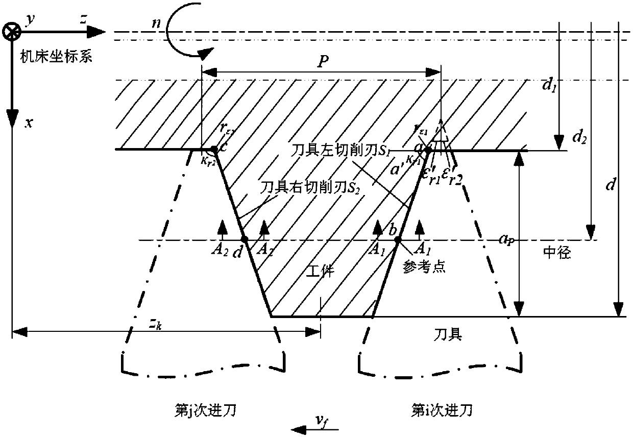
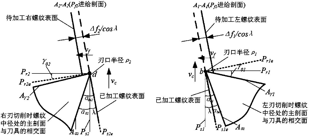
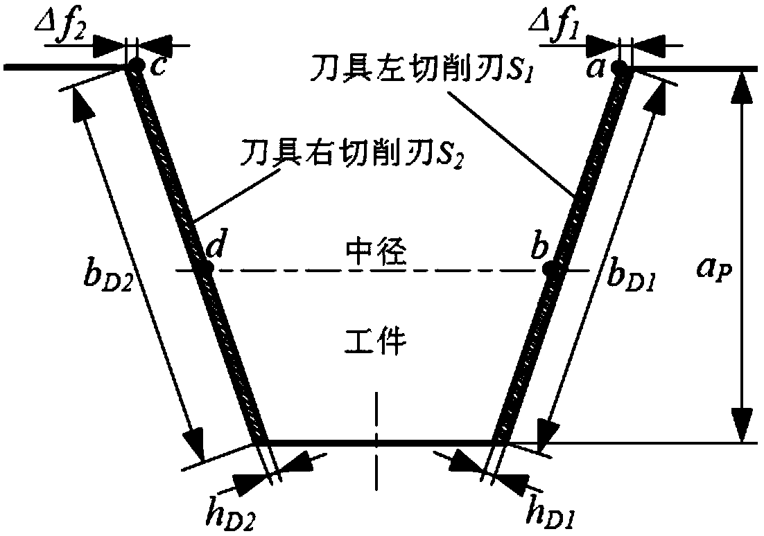
[0049] When cutting the left and right edges of large-pitch threads, because the working angle of the tool is different from the marked angle, the total cutting force and cutting stroke on the left and right edges of the tool are different, which will lead to inconsistent machining results on the left and right edges. During the initial cutting, the motion parameter variables of the left and right cutting edges of the tool are shown in Table 1:

[0050] Table 1 Basic variables of the cutting motion relationship between t...


PUM


Abstract

The invention provides a layer cutting difference analysis method for left and right cutting edges of a cutter and relates to a difference analysis method for cutter cutting. The invention aims to solve the problem that in the prior art, when the left and right cutting edges of a cutter are used in layer cutting of large-pitch threads, difference analysis cannot be performed for the cutting processes of the left and right cutting edges of the cutter, so that the turning process is unstable and the consistency of cut thread flanks is poor. The method comprises the steps of setting the kinematic variables and geometrical variables of the left and right cutting edges of a cutter and obtaining the practical working angle of the cutter according to the geometrical variables; establishing a geometric model of cutter-work piece contact relationship of a base plane and a main section and determining a cutting layer parameter; establishing stressing models in the cutting processes of the left and right cutting edges and obtaining the relationship between feeding resistance borne by the cutter and main cutting force, the shear angle and the resultant cutting force of the cutter during the cutting of the left and right cutting edges according to the cutting layer parameters. The method can reveal the specific difference in cutting of the left and right cutting edges and provide basis for the improvement of the structural design of cutting edges of cutters and the consistence of left and right flanks of threads.

Description

technical field [0001] The invention relates to a difference analysis method during tool cutting, in particular to a layered cutting difference analysis method for left and right cutting edges of a tool, and belongs to the technical field of cutting difference analysis for left and right cutting edges of a tool. Background technique [0002] As a large-scale press adjustment component, the large-pitch screw controls the parallelism and perpendicularity between the upper mold and the lower mold in the press, which has an important impact on the static and dynamic accuracy of the press machine. Large-pitch threads have large pitches, wide and deep tooth grooves, and long axial lengths. They require high machining accuracy and surface morphology, and the formation process of the thread surface is complex and changeable. The turning process of large-pitch threads generally adopts the method of layered cutting. The axial layered cutting includes two methods: left-edge turning and...

Claims


Application Information

Patent Timeline
Patent Type & Authority Patents(China)
IPC IPC(8): G06F17/50
CPCG06F30/367
Inventor 姜彬赵娇徐彤范一航
Owner HARBIN UNIV OF SCI & TECH
Learn More