Hot riveting device for front cover lock reinforcement plate
A reinforcement plate and lock buckle technology, which is applied in the field of auto parts processing, can solve problems such as rivet percussion bending and riveting difficulties at the end, and achieve the effects of improving consistency, improving the accuracy and quality of hot riveting, and improving versatility
- Summary
- Abstract
- Description
- Claims
- Application Information
AI Technical Summary
Problems solved by technology
Method used
Image
Examples
Embodiment 1
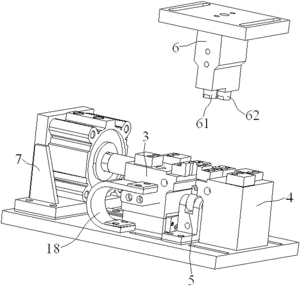
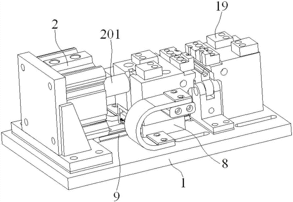
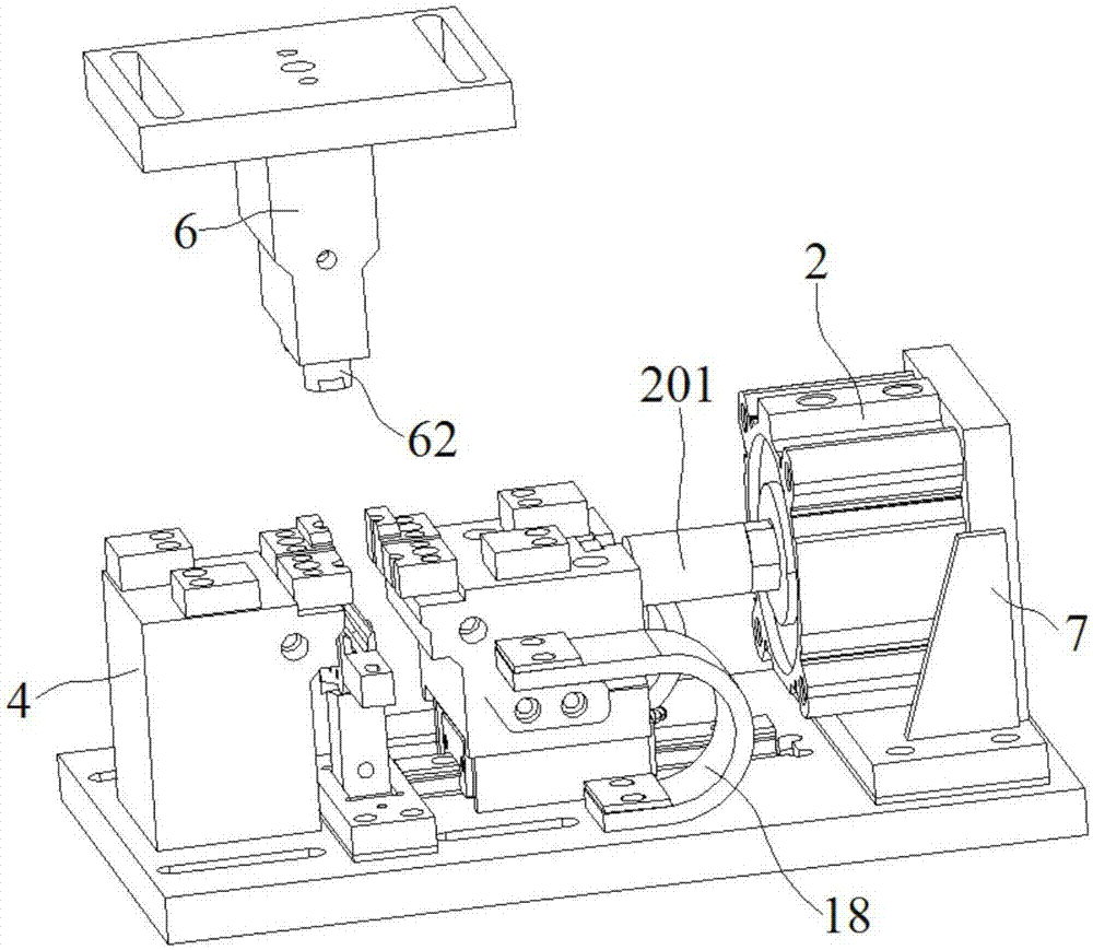
[0021] Embodiment 1: A hot riveting device for a front cover locking reinforcement plate, comprising a base 1, a cylinder 2, a left clamping seat 3, a right clamping seat 4, a positioning mechanism 5 and a riveting head mechanism 6, the A mounting bracket 7 is fixed on the upper surface of one end of the base 1, the cylinder 2 is fixed on the side surface of the mounting bracket 7, the left clamping seat 3 is mounted on a sliding rail 9 through a slider 8, and the right The clamping seat 4 is fixed on the other end of the base 1, the left clamping seat 3 is located between the cylinder 2 and the right clamping seat 4 and the piston rod 201 of the cylinder 2 is connected to the left clamping seat 3, the positioning mechanism 5 Located between the left clamping seat 3 and the right clamping seat 4, the riveting head mechanism 6 is located directly above the positioning mechanism 5, and the riveting piece is placed on the upper surface of the left clamping seat 3 and the right cla...
Embodiment 2
[0025] Example 2: A hot riveting device for a front cover lock reinforcement plate, comprising a base 1, a cylinder 2, a left clamping seat 3, a right clamping seat 4, a positioning mechanism 5 and a riveting head mechanism 6, the A mounting bracket 7 is fixed on the upper surface of one end of the base 1, the cylinder 2 is fixed on the side surface of the mounting bracket 7, the left clamping seat 3 is mounted on a sliding rail 9 through a slider 8, and the right The clamping seat 4 is fixed on the other end of the base 1, the left clamping seat 3 is located between the cylinder 2 and the right clamping seat 4 and the piston rod 201 of the cylinder 2 is connected to the left clamping seat 3, the positioning mechanism 5 Located between the left clamping seat 3 and the right clamping seat 4, the riveting head mechanism 6 is located directly above the positioning mechanism 5, and the riveting piece is placed on the upper surface of the left clamping seat 3 and the right clamping ...
PUM
 Abstract
Description
Claims
Application Information
 - R&D
- Intellectual Property
- Life Sciences
- Materials
- Tech Scout
- Unparalleled Data Quality
- Higher Quality Content
- 60% Fewer Hallucinations
Browse by: Latest US Patents, China's latest patents, Technical Efficacy Thesaurus, Application Domain, Technology Topic, Popular Technical Reports.
© 2025 PatSnap. All rights reserved.Legal|Privacy policy|Modern Slavery Act Transparency Statement|Sitemap|About US| Contact US: help@patsnap.com


