Steam iron

A steam and iron technology, applied in the direction of hand irons, textiles and papermaking, household appliances, etc., can solve the problems of unexpected and uneasy users

Active Publication Date: 2016-08-17
KONINKLJIJKE PHILIPS NV
View PDF7 Cites 2 Cited by
  • Summary
  • Abstract
  • Description
  • Claims
  • Application Information

AI Technical Summary

Problems solved by technology

This can lead to an undesired ejection of steam being generated which can be disturbing or surprising to the user

Method used


Image

  • Steam iron
  • Steam iron
  • Steam iron

Examples


Embodiment Construction

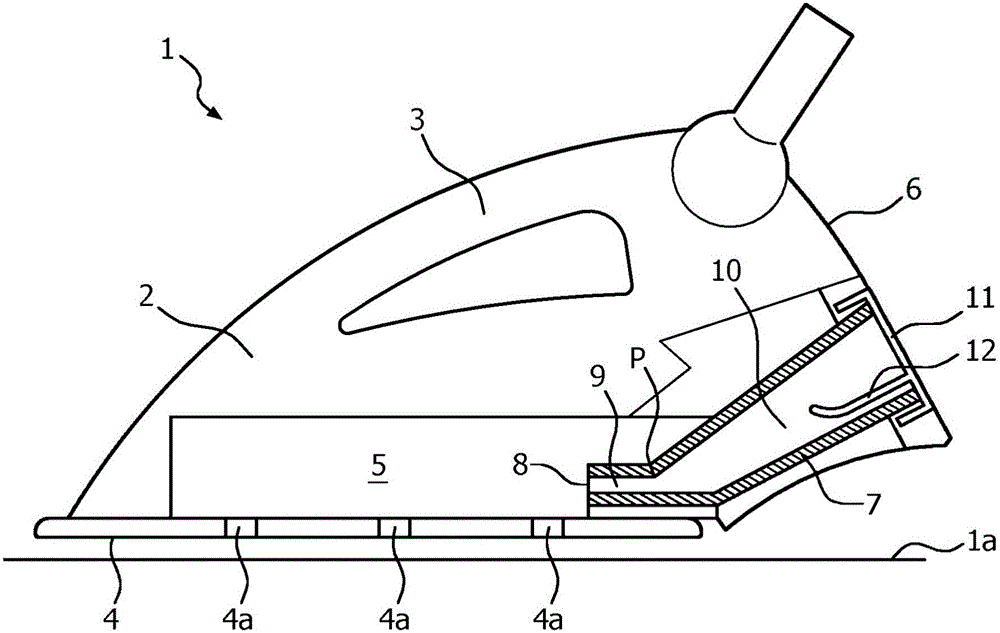
[0027] A steam iron 1 according to an embodiment of the present invention is illustrated in figure 1 and includes a housing 2 with an integral handle 3 . The soleplate 4 is mounted to the housing 2 and is electrically heated to remove wrinkles from the garment when the garment is laid flat on a flat surface such as the ironing board 1a and the soleplate 4 is pressed against and moved across the garment. The steam iron 1 is also provided with a reservoir (not shown) in the housing 2 to contain water for supply to a steam generator 5 located in the soleplate 4 for generating steam for passing through the soleplate 4 The dispensing opening 4a passes to assist wrinkle removal. Alternatively, the reservoir may be placed outside the housing, for example in a separate base, and the water conveyed to the steam generator via a hose.

[0028] figure 1 The steam iron is shown in a typical in-use or ironing position with the soleplate 4 facing downwards so that the weight of the iron 1...


PUM


Abstract

The present application relates to a steam iron comprising a steam generator and a sealed chamber having an inlet positioned so that calcified deposits formed in the steam generator fall under the influence of gravity through said inlet and into the chamber when the iron is moved from an ironing position into a non-ironing position. The chamber includes an inlet conduit that extends from the inlet and leads into a collection reservoir. The inlet conduit is configured so that water which flows from the steam generator into the collection reservoir through the inlet conduit when the iron is placed in said non-ironing position is trapped in the chamber when the iron is moved back into said ironing position. This occurs due to a balance of pressures between water in the collection reservoir, which acts against water that fills the inlet conduit, and atmospheric pressure that acts against water that fills the inlet conduit across the inlet.

Description

technical field [0001] The invention relates to a steam iron having a chamber to receive calcified deposits. Background technique [0002] A steam iron has a housing with a handle, a heel on which the iron rests when not in use, and a heated soleplate to remove wrinkles from clothing. The steam iron also has a reservoir to contain water which is supplied to the steam generator to generate steam which is sprayed onto the clothes through steam distribution openings in the soleplate to assist in wrinkle removal when the clothes are ironed. [0003] A conventional steam iron may be provided with a chamber in or attached to the soleplate positioned to receive the steam formed in the steam generator as a result of the steam generating process, especially when the water used to generate the steam is hard. Calcified deposits, often called "scale". Typically, the chamber is positioned towards the rear of the iron so that whenever the iron is placed on its heel, the calcified deposi...

Claims


Application Information

Patent Timeline
Patent Type & Authority Applications(China)
IPC IPC(8): D06F75/18
CPCD06F75/18
Inventor S·K·陈E·H·谭杜瑞祥J·戈
Owner KONINKLJIJKE PHILIPS NV
Why Eureka
Try Eureka