Multi-way reversing valve

A multi-way reversing valve and reversing valve technology, which is applied in the field of hydraulic valves, can solve the problems of restricting the use and development of hydraulic systems, insufficient compact structure, and large valve group volume, and achieve easy promotion, compact structure, and internal flow channels. simple effect

Inactive Publication Date: 2017-06-13
LOVOL HEAVY IND +1
5 Cites 0 Cited by

AI-Extracted Technical Summary

Problems solved by technology

[0004] At present, the principle of this method is complicated, the volume of the valve group is large, and the structure is not compact enough. In addition, due to the complexity of the flow ...

Method used

Hydraulic control center unloading valve 2, three-position four-way electromagnetic reversing valve unit 4 and three-position four-way manual reversing valve unit 3 are all arranged in different monomers, and thes...

Abstract

The invention discloses a multi-way reversing valve, which includes a reversing valve unit, the oil inlet of the reversing valve unit communicates with the main oil inlet oil circuit, and the oil return port of the reversing valve A hydraulically controlled neutral unloading valve is set between the main oil inlet oil circuit and the main oil return oil circuit, and the control oil port of the hydraulically controlled neutral unloading valve is connected to the reversing valve unit The working oil port of the reversing valve unit is connected; in the neutral state, the oil inlet port of the reversing valve unit is disconnected from the working oil port. The switching of each action of the reversing valve is stable and reliable, the internal structure is simple and compact, the pressure loss is small, and the cost is low.

Application Domain

Servomotor components

Technology Topic

Return channelEngineering +3

Image

  • Multi-way reversing valve
  • Multi-way reversing valve
  • Multi-way reversing valve

Examples

  • Experimental program(2)

Example Embodiment

[0024] Example one
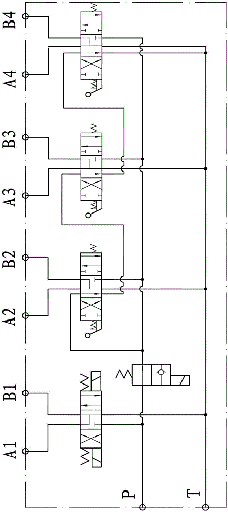
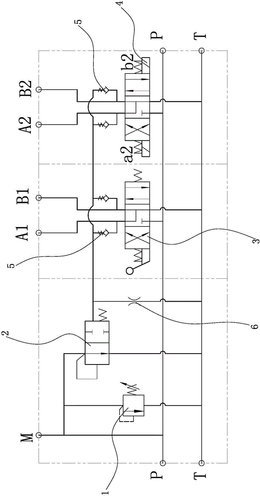
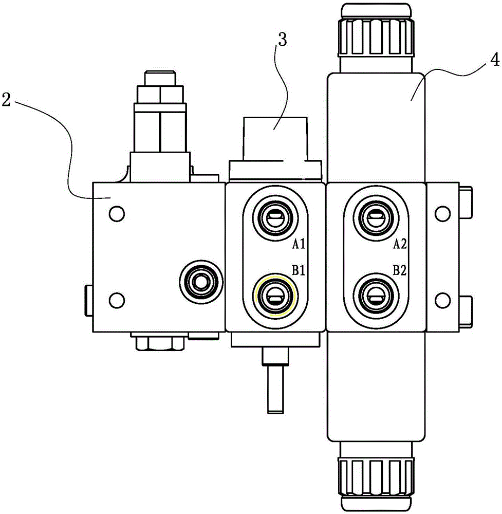
[0025] Such as figure 2 As shown, a multi-way directional valve includes a three-position four-way electromagnetic directional valve unit 4, the oil inlet of the three-position four-way electromagnetic directional valve unit 4 communicates with the main oil inlet oil path, and the three-position four-way electromagnetic directional valve unit 4 The oil return port of the directional valve unit 4 communicates with the main oil return oil path. In the neutral state, the oil inlet of the three-position four-way solenoid directional valve unit 4 is disconnected from the working oil port. In this embodiment, the spool valve performance code of the working position function of the three-position four-way electromagnetic directional valve unit 4 is "Y".
[0026] The three-position four-way manual reversing valve unit 3 is connected in parallel with the three-position four-way electromagnetic reversing valve unit 4. The oil inlet of the three-position four-way manual reversing valve unit 3 is connected to the main oil inlet, and the three-position four-way manual The oil return port of the directional valve unit 3 communicates with the main oil return oil path. In the neutral state, the oil inlet of the three-position four-way manual reversing valve unit 3 is disconnected from the working oil port. In this embodiment, the spool valve performance code of the working position function of the three-position four-way manual reversing valve unit 3 is "Y".
[0027] A hydraulic control neutral unloading valve 2 is arranged between the main oil inlet oil circuit and the main oil return oil channel, and the hydraulic control neutral unloading valve 2 is a two-position two-way valve. The control oil port of the hydraulic control neutral unloading valve 2 is in communication with the working oil port of the three-position four-way electromagnetic reversing valve unit 4. A check valve 5 is arranged between the working oil port of the three-position four-way electromagnetic reversing valve unit 4 and the control oil port of the hydraulic control neutral unloading valve 2. The control oil port of the hydraulic control neutral unloading valve 2 is in communication with the working oil port of the three-position four-way manual reversing valve unit 3. A check valve 5 is provided between the working oil port of the three-position four-way manual reversing valve unit 3 and the control oil port of the hydraulic control neutral unloading valve 2. An overflow valve is provided between the oil inlet of the hydraulic control neutral unloading valve 2 and the main oil return path. A throttle valve 6 is provided between the control oil port of the hydraulic control neutral unloading valve 2 and the main oil return path.
[0028] The hydraulic control neutral unloading valve 2, the three-position four-way electromagnetic reversing valve unit 4, and the three-position four-way manual reversing valve unit 3 are all set in different monomers. Way reversing valve (such as image 3 (Shown), the cartridge structure can improve the versatility of the multi-way directional valve.
[0029] The working principle of this multi-way directional valve is:
[0030] When the three-position four-way solenoid directional valve unit 4 is in the neutral position, there is no load on the working oil ports A2, B2 and T port, the one-way valve 5 does not operate, and the hydraulic control neutral unloading valve 2 has no load sensing area. pressure. When the pressure generated by the pressure oil at the oil inlet P on the spool of the hydraulic control neutral unloading valve 2 exceeds the setting value of the hydraulic control neutral unloading valve 2 spring, it will push the hydraulic control neutral unloading valve 2 valve The rod moves to the right, the spring is compressed, the P port is connected to the T port through the hydraulic control neutral unloading valve 2, the pressure oil is unloaded and the oil is returned, and the overflow valve plays a protective role.
[0031] When the valve stem of the three-position four-way solenoid valve unit 4 moves to the left, the P port hydraulic oil enters the A2 port, and the B2 port communicates with the T port. When the pressure at port A2 exceeds the set value, open the one-way valve 5 and communicate with the spring chamber of the one-way valve 5 and the hydraulic control neutral unloading valve 2. At this time, the hydraulic oil in the left cavity of the hydraulic control neutral unloading valve 2 is opposite to the valve The force of the core is less than the sum of the hydraulic oil in the spring cavity of the hydraulic control neutral unloading valve 2 and the force of the spring on the spool, so the hydraulic control neutral unloading valve 2 valve stem moves to the left, and the hydraulic control neutral position The oil circuit of the unloading valve 2 is disconnected. The pressure oil controls the actuator after passing through the three-position four-way electromagnetic reversing valve unit 4. When the valve stem of the three-position four-way electromagnetic reversing valve unit 4 moves to the right, the principle is the same as when the valve stem of the three-position four-way electromagnetic reversing valve unit 4 moves to the left, and will not be repeated here.
[0032] The working principle of the three-position four-way manual reversing valve unit 3 is similar to the working principle of the three-position four-way electromagnetic reversing valve unit 4, and will not be repeated here.

Example Embodiment

[0033] Example two
[0034] The structure of the second embodiment is basically the same as that of the first embodiment. The difference is that a shuttle valve 7 is provided between the working oil port of the three-position four-way electromagnetic reversing valve unit 4 and the control oil port of the hydraulic control neutral unloading valve 2. A shuttle valve 7 is provided between the working oil port of the three-position four-way manual reversing valve unit 3 and the control oil port of the hydraulic control neutral unloading valve 2, such as Figure 4 Shown.
[0035] The multi-way reversing valve of the first embodiment and the second embodiment can be used in, but not limited to, harvesting machinery such as corn harvesters. Among them, the oil cylinder of the ear picking table is controlled by the three-position four-way electromagnetic reversing valve unit 4.

PUM

no PUM

Description & Claims & Application Information

We can also present the details of the Description, Claims and Application information to help users get a comprehensive understanding of the technical details of the patent, such as background art, summary of invention, brief description of drawings, description of embodiments, and other original content. On the other hand, users can also determine the specific scope of protection of the technology through the list of claims; as well as understand the changes in the life cycle of the technology with the presentation of the patent timeline. Login to view more.

Similar technology patents

Independent micro-grid stability control method based on switching system

PendingCN112838617Asmooth switching
Owner:LIAONING UNIVERSITY OF TECHNOLOGY

Clock switching circuit of gigabit Ethernet transceiver

ActiveCN111313869Asmooth switchingAvoid the risk of glitches and metastability
Owner:XIAN MICROELECTRONICS TECH INST

Automobile active air-inlet grille limiting structure

PendingCN112757894AThe limit structure is simpleSmooth switching
Owner:CHENGDU AEROSPACE MOLD & PLASTIC CO LTD

Camera module switching control method and device and storage medium

PendingCN114157801ASmooth switching
Owner:BEIJING XIAOMI MOBILE SOFTWARE CO LTD

Classification and recommendation of technical efficacy words

  • smooth switching
  • Simple working principle

Resolution switching method and device of video

InactiveCN106375836ASmooth switchingImprove experience
Owner:GUANGDONG XIAOTIANCAI TECH CO LTD

Automatic control method for air-fuel ratio of hot-blast stove

InactiveCN105783024ABurn fullysmooth switching
Owner:WISDRI ENG & RES INC LTD

Method and device for achieving smooth switching of panoramic views in panoramic roaming

InactiveCN105869201Asmooth switching
Owner:BEIJING PANOTHINK TECH CO LTD

Panorama content playing method and device

ActiveCN106254940Asmooth switching
Owner:BEIJING MADV TECH CO LTD +1

Detecting device and detecting method for surface evenness of gate

ActiveCN104776823ASimple working principleImprove adaptability
Owner:HOHAI UNIV

Adjustable revolution axis mechanism and electronic product having the same

InactiveCN101309566ASimple working principleSimple component structure
Owner:GUANGZHOU LUXVISIONS INNOVATION TECH LTD

Gas separating device and gas separating method

ActiveCN103277131ASimple working principleSimple structure
Owner:CHNA ENERGY INVESTMENT CORP LTD +2

Resistance-type concrete abrasion sensor and measurement method thereof

InactiveCN102141369ASimple working principleEasy to measure
Owner:POWERCHINA ZHONGNAN ENG
Why Eureka
Try Eureka