A test tube holding device

A clamping device and test tube technology, applied in the direction of test tube brackets/clamps, etc., can solve the problems of high risk, high equipment cost, and no provision, and achieve the effect of solving disinfection and sterilization resources, reducing experimental risks, and having a simple structure.

Active Publication Date: 2018-09-28
无锡锡东大学生创业孵化管理有限公司
View PDF7 Cites 0 Cited by
  • Summary
  • Abstract
  • Description
  • Claims
  • Application Information

AI Technical Summary

Problems solved by technology

[0002] In the strain test, aseptic operation is often required, and the test volume is large, and individual test tubes may need to be adjusted during the test process. Pick and place a single test tube by hand. On the one hand, it is extremely wasteful and inconvenient to perform complex disinfection and sterilization operations for the operator to enter the sterile environment for occasional adjustments. On the other hand, due to the limited hand length , which also leads to the inability to maximize the use of space in the placement of test tubes
There are also mechanical devices for picking and placing test tubes in the prior art, but they generally adopt fully automated operations. Equipment providers generally do not provide separate test tube picking and placing equipment, and the price of a complete set of equipment is too high for small and medium-sized enterprises.
All of the above have resulted in high costs and high risks for small and medium-sized enterprises in bulk strain experiments, which also makes it difficult for small and medium-sized enterprises to effectively use even if they have high-end talents.
[0003] For example, the Chinese invention patent whose patent number is CN201120576509.2 discloses a clamping body of a test tube clamping device, which uses a support body, a clamp rotating piece and a rubber sheet to complete the clamping operation of a single test tube. Obviously, the actual product of this technology is not It may be provided separately, but the cost of the whole set of equipment is relatively high. Small and medium-sized enterprises must bear such a high cost that the cost will be too high, so they will inevitably bear high pressure on funds, thereby increasing the operational risk of the enterprise.

Method used


Image

  • A test tube holding device
  • A test tube holding device
  • A test tube holding device

Examples


Embodiment Construction

[0016] The technical solution of the present invention is further described below, but the scope of protection is not limited to the description.

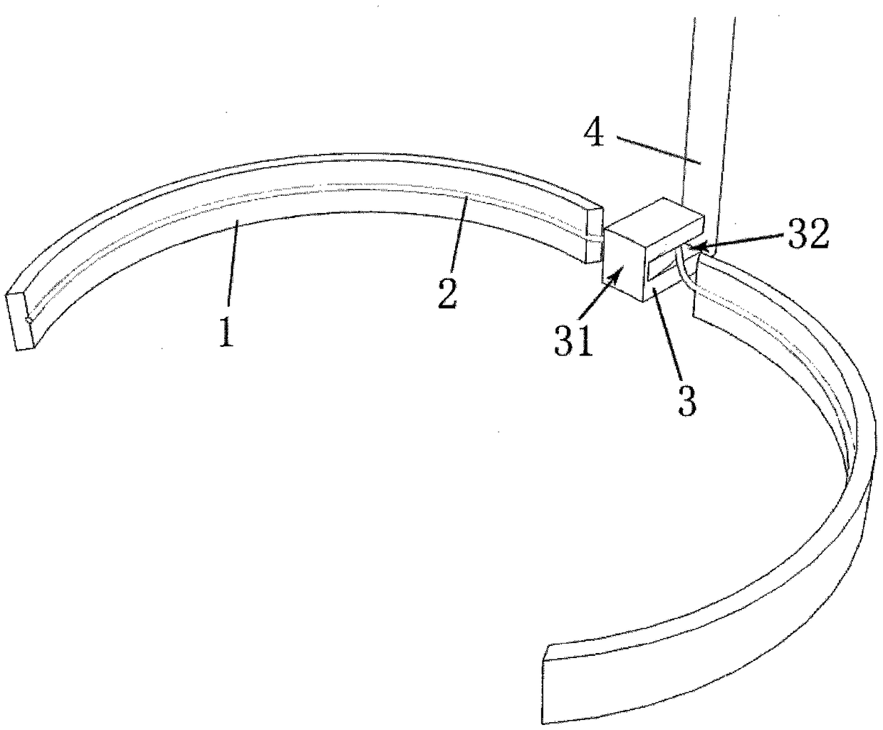
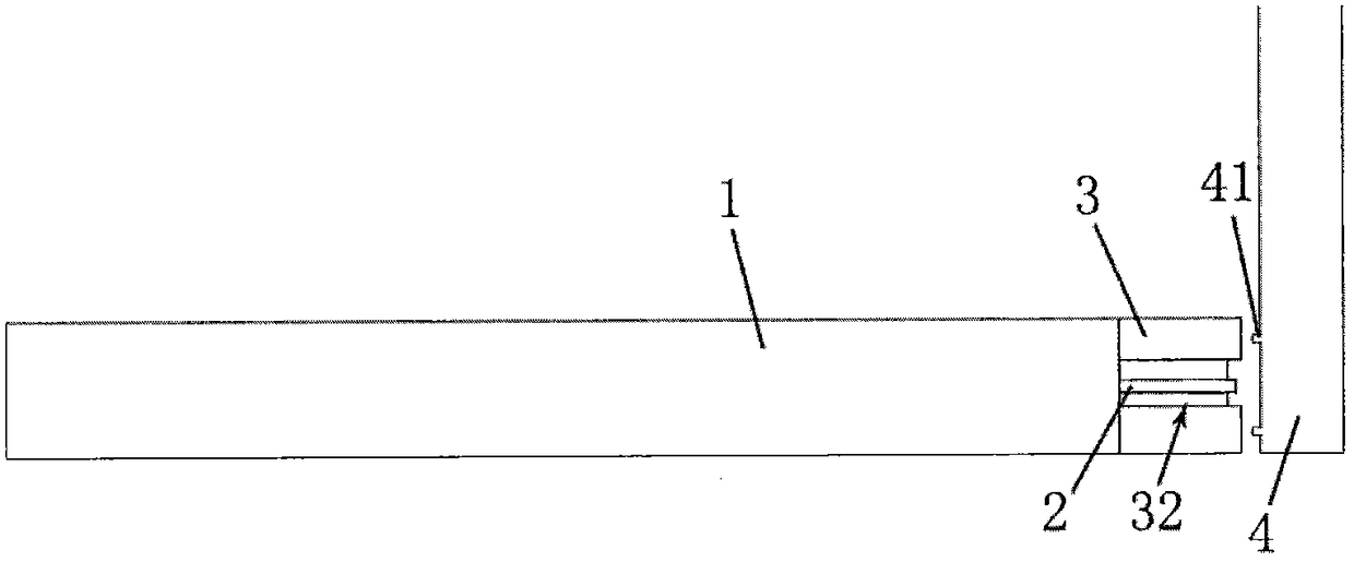
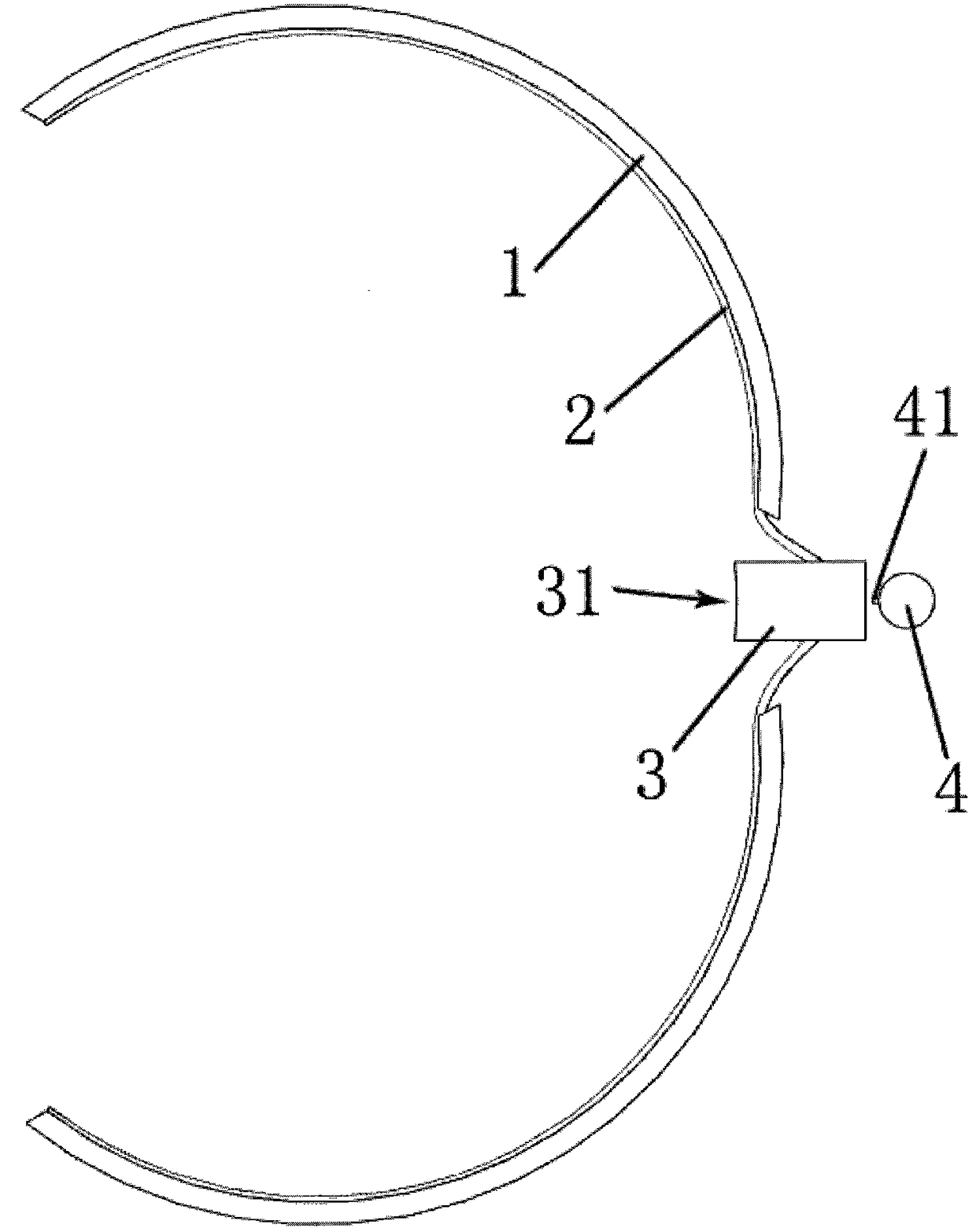
[0017] Such as Figure 1 to Figure 3 A test tube clamping device shown includes a clamping ring 1, a tension belt 2, a moving block 3, and a pole 4; the clamping ring 1 is an arc-shaped half ring with an angle less than 150°, and the number is two , the two clamping rings 1 are horizontally oppositely arranged; the moving block 3 is arranged in the middle of one end of the two clamping rings 1, and is connected with the proximal ends of the two clamping rings 1; the strut 4 is vertically arranged, The moving block 3 is movably fixed on the bottom of the pole 4, and the movable direction of the moving block 3 is perpendicular to the radial direction of the pole 4; 1 and the moving block 3 are set towards the pole 4 side.

[0018] When in use, you only need to set the top of the support rod 4 on the top cross bar of the laboratory,...


PUM


Abstract

The invention provides a test tube clamping device. The test tube clamping device comprises clamping rings, a tensioning belt, a movable block and a supporting rod, wherein each clamping ring is an arc-shaped semi-ring with an angle smaller than 150 degrees, and the two clamping rings are arranged; the two clamping rings are arranged horizontally and oppositely; the movable block is arranged between edge end parts of the two clamping rings and is close to rear ends of the two clamping rings; the supporting rod is vertically arranged; the movable block is movably fixed at the bottom of the supporting rod; the movable direction of the movable block is vertical to the radial direction of the supporting rod; and the tensioning belt is fixed at the rear ends of the clamping rings and is arranged along the inner sides of the clamping rings, and the movable block is arranged toward one side of the supporting rod. Non-manual operation of separately taking tubes in a sterile environment is realized through a pure mechanical, low-cost and easily-maintaining manner and is stable and reliable; experiment risks can be effectively reduced, and disinfection and sterilization resources are solved; and the test tube clamping device is simple in structure and easy to maintain, and provides reliable guarantees to large-batch strain experiments of middle-size and small-size enterprises.

Description

technical field [0001] The invention relates to a test tube clamping device. Background technique [0002] In the strain test, aseptic operation is often required, and the test volume is large, and individual test tubes may need to be adjusted during the test process. Pick and place a single test tube by hand. On the one hand, it is extremely wasteful and inconvenient to perform complex disinfection and sterilization operations for the operator to enter the sterile environment for occasional adjustments. On the other hand, due to the limited hand length , Also cause the placement of test tubes to fail to maximize the use of space. There is also a mechanical device for picking and placing test tubes in the prior art, but that is generally fully automated. Equipment providers generally do not provide separate test tube picking and placing equipment, and the price of a complete set of equipment is too high for small and medium-sized enterprises. All of the above have resulted...

Claims


Application Information

Patent Timeline
Patent Type & Authority Patents(China)
IPC IPC(8): B01L9/06
Inventor 张晶磊王信刚骆寿英
Owner 无锡锡东大学生创业孵化管理有限公司
Why Eureka
Try Eureka