Rail clamping device

A technology of rail clamps and splints, which is applied in the direction of traveling mechanism, load hanging components, transportation and packaging, etc. It can solve the problems of affecting work efficiency, easy damage of rail clamps, and affecting maintenance work, etc., and achieves the effect of convenient disassembly and maintenance

Inactive Publication Date: 2016-08-24
HEFEI SHENDIAO HOISTING MACHINERY
View PDF6 Cites 0 Cited by
  • Summary
  • Abstract
  • Description
  • Claims
  • Application Information

AI Technical Summary

Problems solved by technology

[0002] Traditional gantry cranes use handwheel screw rail clamps. This kind of rail clamp is very easy to damage, and it is also very tro

Method used


Image

  • Rail clamping device
  • Rail clamping device
  • Rail clamping device

Examples


Example Embodiment

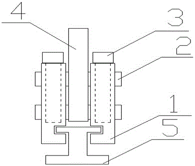
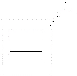
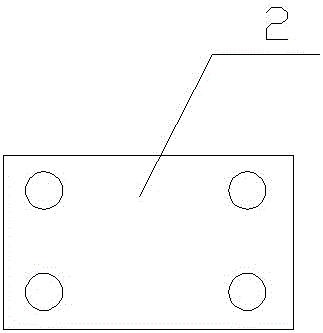
[0013] Such as figure 1 As shown, the present invention discloses a rail clamp, which includes a clamp plate 1, a limit plate 2, a bolt 3, a fixing plate 4, and a rail 5. A "U"-shaped slide rail is opened at the lower end of the left plane of the clamp plate 1. The upper end of the "U"-shaped slide rail hole is provided with two vertical rectangular holes, and the size of the two rectangular holes on the splint 1 is exactly the same, and the same is placed on the left end of the splint 1 Splint 1, and the "U"-shaped slide rail holes of the two splints 1 are opposite, the two splints 1 just clamp the upper end of the rail 5, and the two splints 1 are connected by the limit plate 2 and connected by the bolt 3. The limiting plate 2 is fixed, and the two limiting plates 2 have two rectangular parallelepiped holes passing through the fixing plate 4.

[0014] The distance between the two splints is equal to the width of the fixed plate

[0015] The present invention is implemented as fo...


PUM


Abstract

The invention discloses a rail clamping device which comprises clamping plates, limiting plates, bolts, a fixing plate and a rail. 'U'-shaped slide rail holes are formed in the lower ends of left planes of the clamping plates, two cuboid-shaped holes in the vertical directions are formed in the upper end of each 'U'-shaped slide rail hole and have completely identical sizes, identical clamping plate bodies are arranged at the left ends of the clamping plates, the 'U'-shaped slide rail holes of the two clamping plates are opposite to each other, the two clamping plates are exactly clamped at the upper end of the rail and are connected with each other by the limiting plates, and the two limiting plates are fixed by the aid of the bolts and penetrate two cuboid-shaped holes of the fixing plate. The rail clamping device has the advantages of convenience in mounting, detaching and maintaining, and the like.

Description

technical field [0001] The invention relates to a rail clamp, in particular to a rail clamp. Background technique [0002] Traditional gantry cranes use handwheel screw rail clamps. This kind of rail clamp is very easy to damage, and it is also very troublesome to operate. It increases the difficulty of construction, affects the overall work efficiency, and also affects maintenance work. Contents of the invention [0003] In order to solve the defects of the prior art solutions, the invention discloses a rail clamp which is convenient for installation and disassembly for maintenance. [0004] The invention discloses a rail clamp, comprising: a splint, a limiting plate, bolts, a fixing plate, and a track. The lower end of the left plane of the splint is provided with a "U"-shaped slide rail hole, and the "U"-shaped The upper end of the slide rail hole is provided with two vertical rectangular parallelepiped holes, and the size of the two rectangular holes on the splint is ...

Claims


Application Information

Patent Timeline
IPC IPC(8): B66C9/18
CPCB66C9/18
Inventor 罗晓虎
Owner HEFEI SHENDIAO HOISTING MACHINERY
Why Eureka
Try Eureka