High power gas catalytic burner

A gas catalysis and burner technology, which is applied to gas fuel burners, burners, combustion methods, etc., can solve the problems of complex structure of high-power catalytic burners, difficulty in uniform preheating of catalyst carriers, and failure of catalytic burners to work normally. , to achieve the effect of compact structure, volume reduction and cost reduction

Inactive Publication Date: 2007-10-10
北京建筑工程学院 +1
View PDF3 Cites 13 Cited by
  • Summary
  • Abstract
  • Description
  • Claims
  • Application Information

AI Technical Summary

Problems solved by technology

On the other hand, the flow rate distribution of the fully premixed gas through the catalyst carrier must be uniform, otherwise the local temperature will be too high, resulting in local catalyst deactivation and the entire catalytic burner cannot work normally
Because the catalyst is limited by the high temperature limit, the combustion intensity per unit area of ​​the catalyst carrier of the catalytic burner cannot be too large. To increase the combustion power, the combustion area can only be increased, but the increase in the combustion area of ​​the catalyst carrier will inevitably lead to uniform preheating of the catalyst carrier. Thermal difficulties make the structure of high-power catalytic burners complex and bulky, making it difficult for industrial applications

Method used


Image

  • High power gas catalytic burner
  • High power gas catalytic burner
  • High power gas catalytic burner

Examples


Embodiment 1

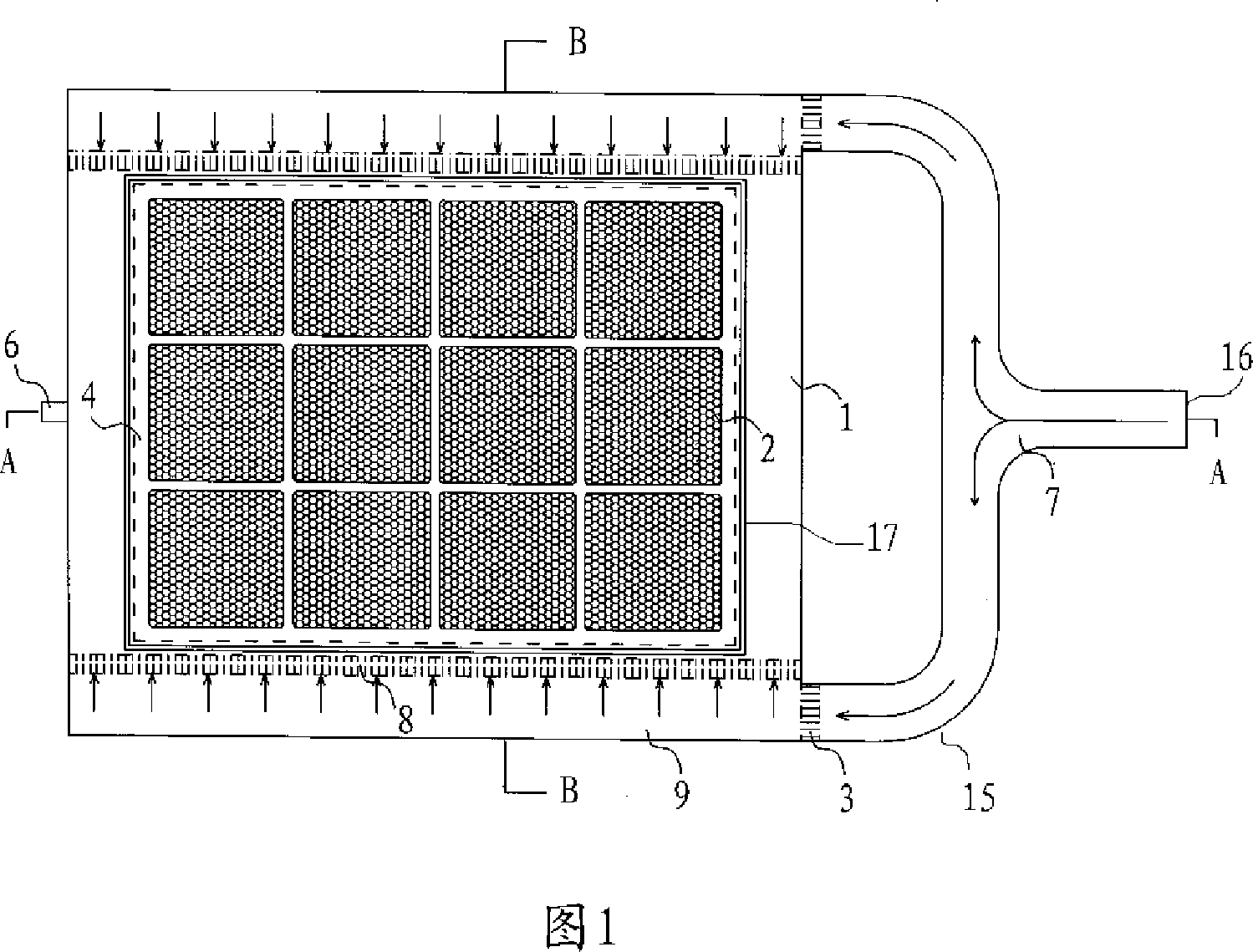
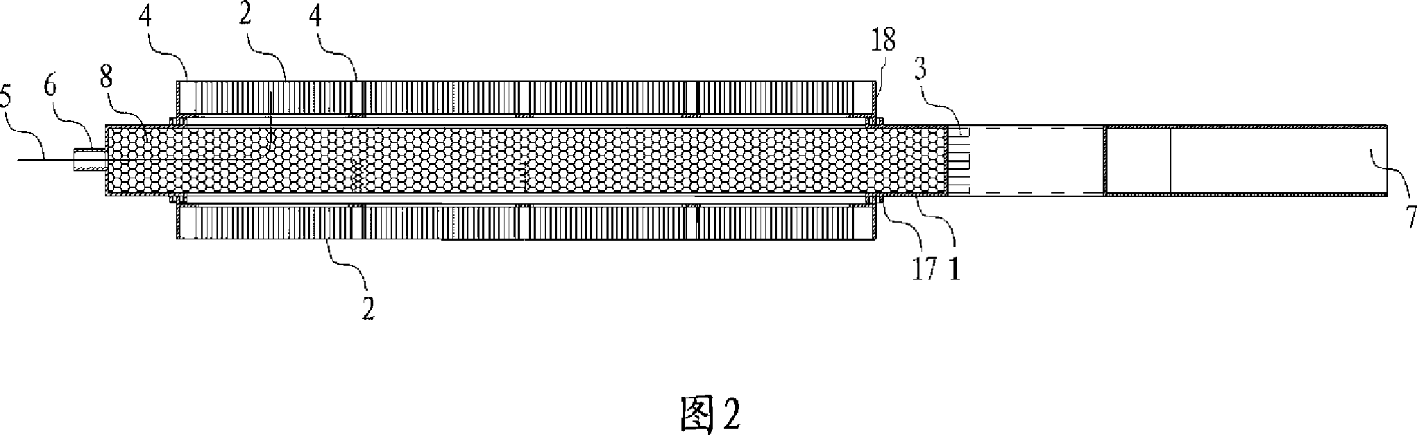
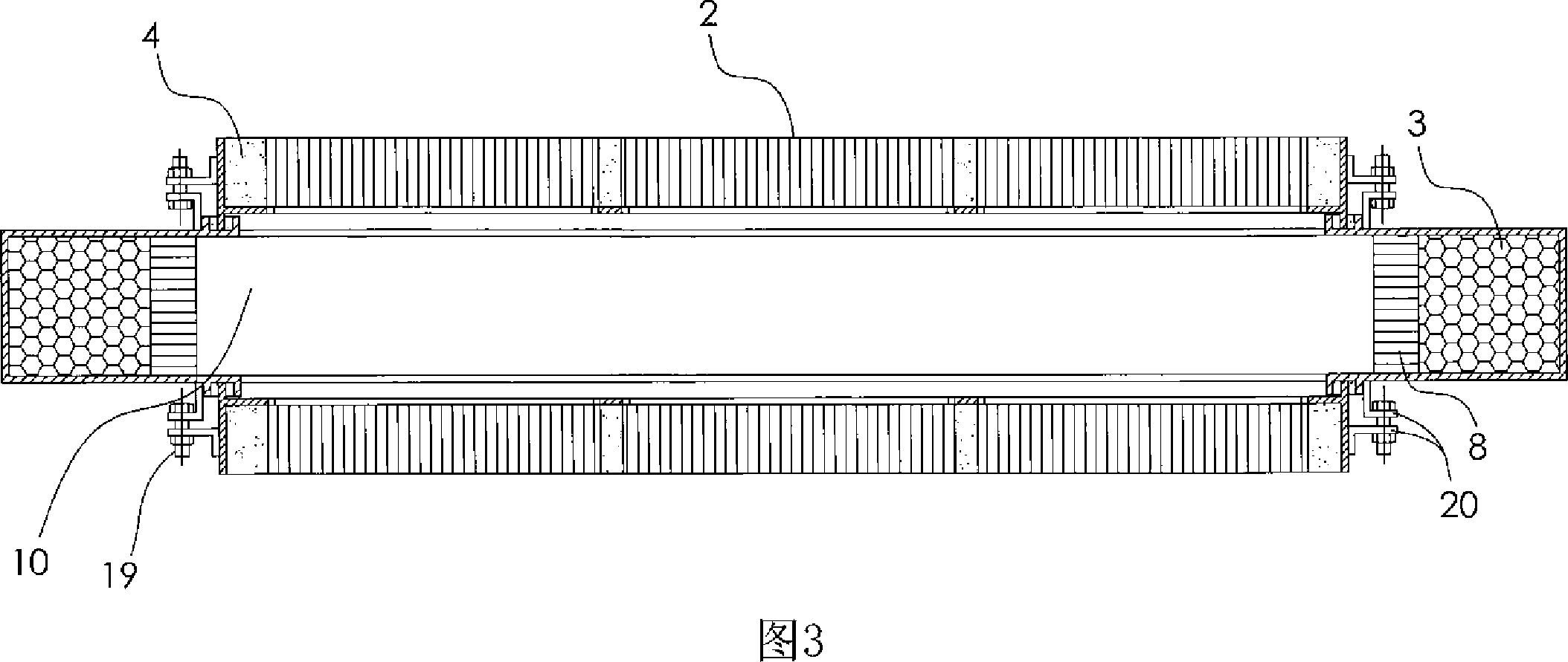
[0034]The structure of the high-power gas catalytic burner in Embodiment 1 is shown in Figures 1 to 3: for this high-power gas catalytic burner, the inlet end 16 of the gas pipeline is connected to one end of the pipeline tee 7, and the pipeline three The other two ends of the channel 7 are respectively in the shape of 90-degree elbows 15, and are connected to the mixed gas channel 9 surrounding the peritoneal cavity of the catalytic burner. Fluid rectifiers are respectively arranged at the inlet and outlet of the mixed gas channel 9. The first fluid rectifier 3 is located at the junction of the pipeline tee 7 and the mixed gas channel 9, and the second fluid rectifier 8 is located at the junction of the mixed gas channel 9 and the abdominal cavity 10 of the burner. A group of catalyst carrier modules 2 placed in the frame 18 are respectively connected to both sides of the burner abdominal cavity 10, and the gaps around each catalyst carrier module are filled with high-temperat...

Embodiment 2

[0047] Fig. 4 is the structural schematic diagram of the non-parallel combination application embodiment of two groups of catalytic burners of the present invention, this is to use two groups of high-power gas catalytic burners and three groups of finned heat exchangers 11 to carry out heat exchange, in order to prevent heat exchanger Condensed water droplets on the catalytic carrier module 2 lead to the actual effect of the catalyst. The catalytic burner adopts a vertical combustion form. Two sets of gas catalytic burners and three sets of heat exchangers are arranged one-to-one. The heating surface of the device is parallel, and the parallel distance is 4cm, which is beneficial to the radiation heat exchange between the catalytic combustion and the heat exchanger. The heat exchangers are connected in series by connecting pipes 14 .


PUM


Abstract

A catalytic burner of large-power fuel gas type is prepared for connecting gas inlet end of gas transmission pipe to one end of T-joint on pipe, connecting the other two ends in form of 90 degree elbow of T-joint to mixed gas channel, arranging fluid rectifier separately at inlet and outlet of mixed gas channel, connecting one set of catalyst carrier porous module set in frame separately to each of double-surface at burner cavity, packing high-temperature resisting insulation material at peripheral gap of said module and extending temperature transducer into said module through a temperature transducer entrance set on external wall of burner cavity.

Description

(1) Technical field [0001] The invention relates to a burner using gas as fuel, in particular to a catalytic burner. (two), background technology [0002] Catalytic combustion uses a catalyst to control the combustion chemical reaction process and release heat under certain conditions, but the catalyst itself is not consumed. Catalytic combustion can reduce activation energy, accelerate necessary chemical reactions, and minimize harmful or unnecessary chemical reactions. At present, the catalytic combustion of natural gas has achieved a combustion efficiency greater than 99.99%, while the harmful substances NOx, CO, and HC emitted by the flue gas are all less than 10×10 -6 , it is very obvious that the combustion efficiency of catalytic combustion is extremely high, and the pollutants are effectively controlled while burning, so catalytic combustion is an ideal and environmentally friendly combustion method. [0003] It is well known that the greenhouse effect of methane e...

Claims


Application Information

Patent Timeline
Patent Type & Authority Applications(China)
IPC IPC(8): F23D14/18
Inventor 周琦王燕京张世红
Owner 北京建筑工程学院
Why Eureka
Try Eureka