Intelligent object return system and bowling pin automatic placement system
A bowling ball and object technology, applied in bowling balls, sports accessories and other directions, can solve the problems of huge and complex bowling equipment, and achieve the effects of practicability and entertainment, high intelligence and simple structure
- Summary
- Abstract
- Description
- Claims
- Application Information
AI Technical Summary
Problems solved by technology
Method used
Image

Examples
specific Embodiment approach 1
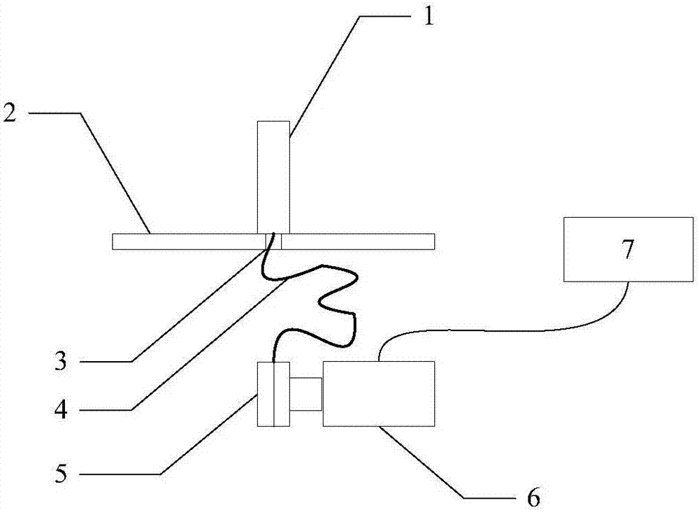
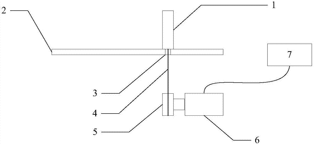
[0025] Refer to attached figure 1 , attached figure 2 And attached image 3 Describe this embodiment. In this embodiment, the invented object return system is composed of an object 1, a placement surface 2, a rope hole 3, a traction rope 4, a rope reel 5, a motor 6 and a control module 7; the object 1 Stand upright on the placement surface 2 or fall away from the placement position; the rope hole 3 is located on the placement surface 2; the traction rope 4 passes through the rope passage hole 3 on the placement surface 2, one end is tied to the bottom surface of the object 1, and the other end Be tied on the rope drum 5; the rope drum 5 is connected to the shaft end of the motor 6, and the traction rope 4 is fixed and wound thereon; the motor 6 is controlled by the control module 7; the control module 7 is used to control the two-way operation of the motor 6 The rotation and stop of the object return system is as follows: first, the object 1 stands on the rope hole 3, and t...
specific Embodiment approach 2
[0026] Refer to attached figure 1 , attached figure 2 And attached image 3 Describe this embodiment, this embodiment is an extension on the basis of specific embodiment 1; in this embodiment, according to the object return system described above, there are multiple objects 1, and there are multiple components related to it, forming Such combination expansion: multiple objects 1 are placed in different positions on the placement surface 2, multiple objects 1 correspond to the same number of rope holes 3, the same number of traction ropes 4, the same number of rope drums 5 and the same number The motor 6 and the control module 7 can be multiple or combined into one; therefore, after all or part of the object 1 is toppled by external force, the same set of motors as the object 1 can be controlled by the control module 7 mentioned above. 6. Drive the rope reel 5 of the same set to tighten the traction rope 4 of the same set, and make the objects 1 of the same set toppled reset...
specific Embodiment approach 3
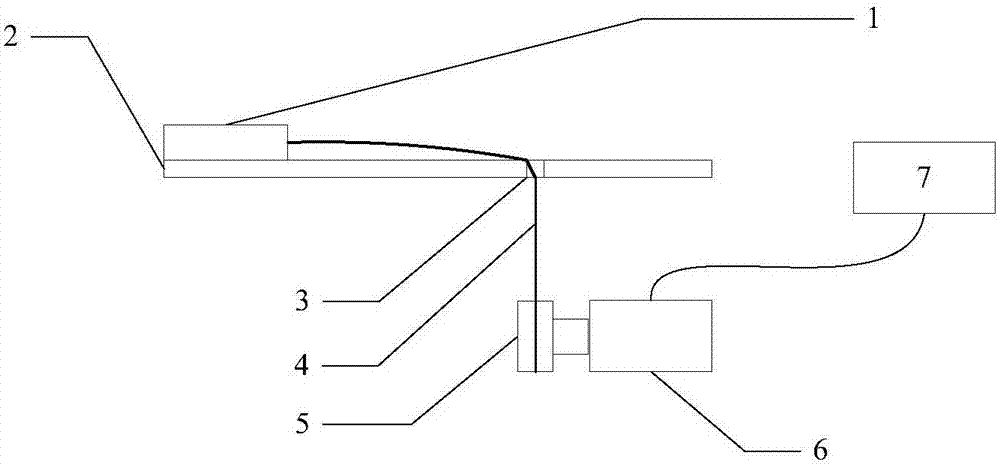
[0027] Refer to attached figure 1 , attached figure 2 , attached image 3 And attached Figure 4 Describe this embodiment, this embodiment is an expansion on the basis of specific embodiment 1 and specific embodiment 2; in this embodiment, according to the object return system described above, a fixing device 8 is added; the fixing device 8 is placed on the traction rope 4, limit the steering angle of the traction rope 4 with the fixing device 8, so that the position of the motor 6 can not only be placed under the placement surface 2, but also be placed in other positions; multiple fixing devices 8 can also be added, and the The above-mentioned combined expansion comprising a plurality of objects 1 together constitutes an expanded object return system comprising a plurality of fixing devices 8 .
PUM
 Abstract
Description
Claims
Application Information
 - R&D
- Intellectual Property
- Life Sciences
- Materials
- Tech Scout
- Unparalleled Data Quality
- Higher Quality Content
- 60% Fewer Hallucinations
Browse by: Latest US Patents, China's latest patents, Technical Efficacy Thesaurus, Application Domain, Technology Topic, Popular Technical Reports.
© 2025 PatSnap. All rights reserved.Legal|Privacy policy|Modern Slavery Act Transparency Statement|Sitemap|About US| Contact US: help@patsnap.com