Shaft transport equipment

A technology for transportation equipment and output terminals, applied in the field of transmission equipment, can solve the problems of time-consuming, labor-intensive, error-prone, and low production efficiency.

Active Publication Date: 2019-11-05
宁波信基机械科技有限公司
View PDF4 Cites 0 Cited by
  • Summary
  • Abstract
  • Description
  • Claims
  • Application Information

AI Technical Summary

Problems solved by technology

After the shaft production is completed, it needs to go through steps such as grinding, cleaning, and storage. For some small transmission shafts, after being polished and cleaned, they are often shaken out of the cleaning equipment by mechanical equipment and dumped on the transportation equipment. The position and direction of the shafts on the equipment appear to be messy and disorganized. At the end of the transport equipment, the staff need to manually adjust the position and direction of these shafts so that the shafts can be transported to the storage place neatly. position, manual operation is time-consuming and labor-intensive, and the labor intensity of the staff is also very high. Over a long period of time, errors are even prone to occur, resulting in low production efficiency

Method used


Image

  • Shaft transport equipment

Examples


Embodiment Construction

[0013] The present invention will be described in further detail below by means of specific embodiments:

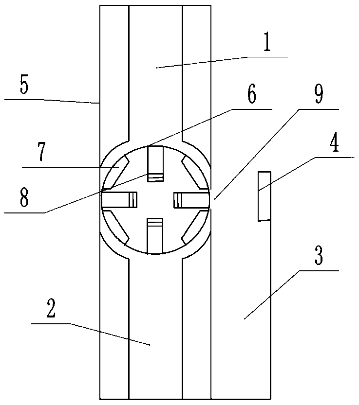
[0014] The reference signs in the accompanying drawings of the description include: the first conveyor belt 1 , the second conveyor belt 2 , the third conveyor belt 3 , the permanent magnet 4 , the baffle plate 5 , the vertical groove 6 , the horizontal groove 7 , the metal plate 8 , and the opening 9 .

[0015] The embodiment is basically as figure 1 Shown:

[0016] The shaft transportation equipment of this embodiment includes a first conveyor belt 1, a turntable between the first conveyor belt 1 and the second conveyor belt 2, vertical grooves 6 are evenly distributed on the circumference of the turntable, and a gap is provided between the two vertical grooves 6. There is a horizontal groove 7, the depth of the vertical groove 6 is equal to the length of the horizontal groove 7 and is equal to the length of the shaft to be transported, a metal plate 8 is slidably conn...


PUM


Abstract

The invention belongs to conveying devices and particularly relates to a shaft conveying device. The shaft conveying device comprises a first conveyer belt. A rotation disk is arranged between the first conveyer belt and the second conveyer belt. Vertical grooves are evenly distributed on the circumference of the rotation disk. A transverse groove is arranged in the interval between every two adjacent vertical grooves. The depth of each vertical groove and the length of each transverse groove are equal and both equal to the length of a shaft needing to be conveyed. Metal plates are connected into the vertical grooves in a sliding manner. A third conveyer belt is arranged on one side of the second conveyer belt. Baffles are arranged on the first conveyer belt and the second conveyer belt. The input end of the third conveyer belt is provided with a support plate. The support plate is provided with a permanent magnet. A connection plate used for limiting is arranged between the first conveyer belt and the second conveyer belt. The side, close to the second conveyer belt, of the connection plate is provided with an opening. The length of the opening is larger than the diameter of the shaft to be conveyed. By the adoption of the shaft conveying device, the shafts can be automatically arranged on the conveying device in order and conveyed to a storage site, the work time is saved, and the efficiency is improved.

Description

technical field [0001] The invention belongs to the field of transmission equipment, and in particular relates to a shaft transportation equipment. Background technique [0002] The shaft (shaft) is a cylindrical object that goes through the middle of the bearing or the middle of the wheel or the middle of the gear. A shaft is a mechanical part that supports and revolves with a rotating part to transmit motion, torque or bending moment. After the shaft production is completed, it needs to go through steps such as grinding, cleaning, and storage. For some small transmission shafts, after being polished and cleaned, they are often shaken out of the cleaning equipment by mechanical equipment and dumped on the transportation equipment. The position and direction of the shafts on the equipment appear to be messy and disorganized. At the end of the transport equipment, the staff need to manually adjust the position and direction of these shafts so that the shafts can be transport...

Claims


Application Information

Patent Timeline
Patent Type & Authority Patents(China)
IPC IPC(8): B65G47/52B65G47/24
CPCB65G47/24B65G47/52B65G2201/02
Inventor 王健
Owner 宁波信基机械科技有限公司
Why Eureka
Try Eureka