Automatic roll stamping seal device

A technology of stamping and rolling printing is applied in the field of automatic rolling stamping and stamping devices, which can solve the problems of complex structure, increased mechanism failure, and high failure probability, and achieves the effects of simple mechanical structure, reduced manufacturing cost, and reduced failure probability.

Active Publication Date: 2010-07-28
CHENGDU JIAYITONG INFORMATION TECH CO LTD
View PDF0 Cites 11 Cited by
  • Summary
  • Abstract
  • Description
  • Claims
  • Application Information

AI Technical Summary

Problems solved by technology

[0003] For the electromagnetic clutch control method, since the clutch is connected to the motor through gears and driven by the motor, in this control structure, the two elements that affect its service life are the motor and the clutch, which increases the probability of mechanism failure. (that is, if any of the components fails, the mechanism will have problems), and at the same time, the price of the electromagnetic clutch is expensive, which increases the cost; The power mechanism and mechanical structure are used to switch between different stamps. The structure is more complicated, and the electromagnet power mechanism, like the motor, has a limited service life. Therefore, this set of mechanisms has a high probability of failure, because one more will fail. Components - electromagnet power mechanism, at the same time, due to its relatively complex structure, it increases the processing cost of parts and the production cost of the device; Only through it can it be fixed and installed. The installation method is not flexible, and it involves seal replacement and inconvenient maintenance.

Method used


Image

  • Automatic roll stamping seal device
  • Automatic roll stamping seal device
  • Automatic roll stamping seal device

Examples


Embodiment Construction

[0019] The present invention will be further described below in conjunction with the accompanying drawings.

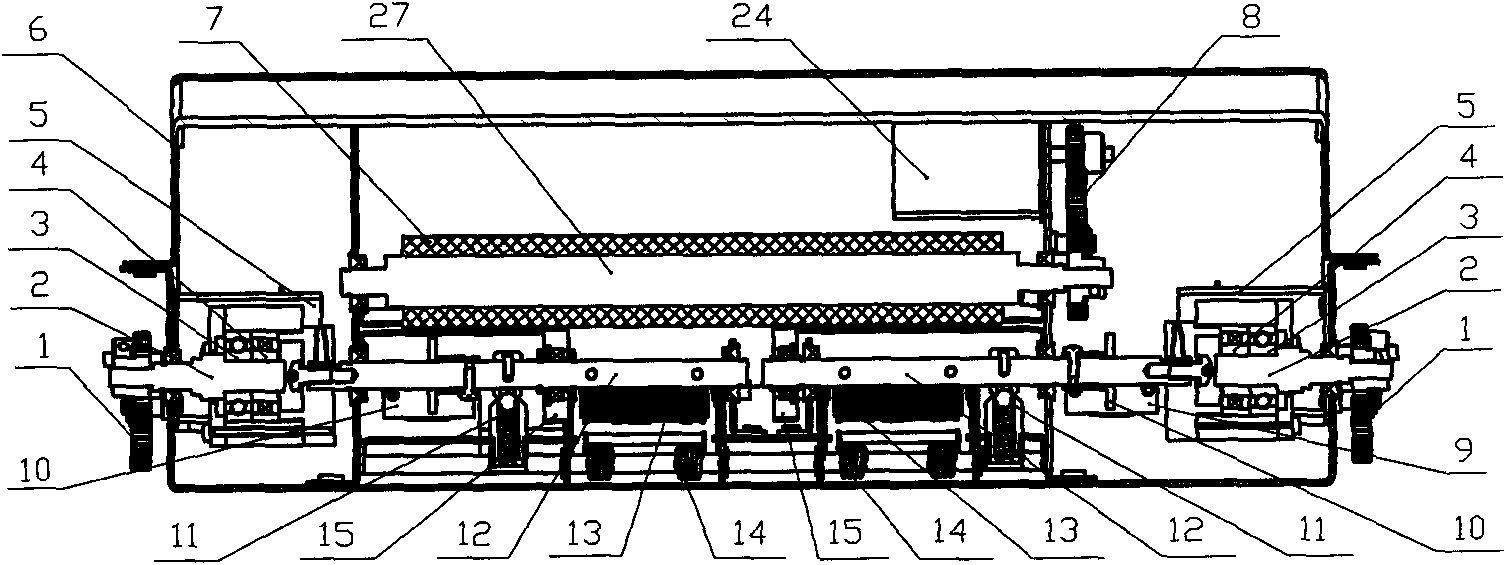
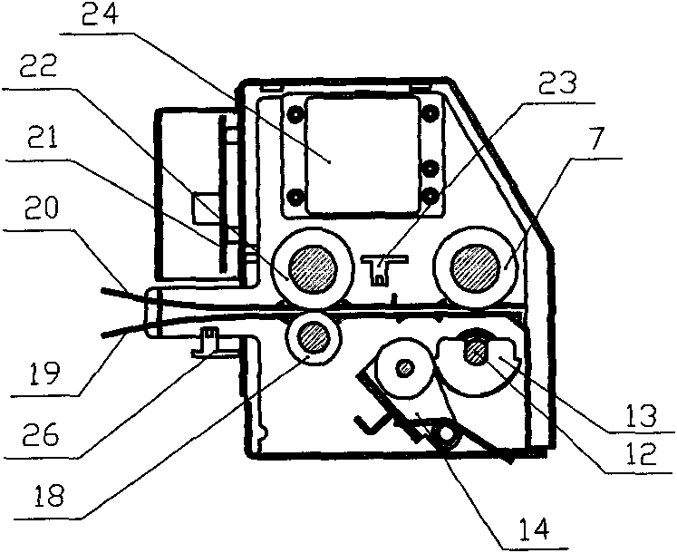
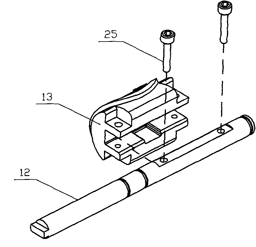
[0020] Such as Figure 1 to Figure 3 As shown, the automatic roll printing and stamping device of the present invention includes a paper feed channel, and the seal rotating shaft 12 and the rolling printing rotating shaft 27 arranged on both sides of the paper feeding channel, the seal rotating shaft 12 and the rolling printing rotating shaft 27 form a rotating shaft system, and the seal rotating shaft 12 is provided with rolling stamp 13, and rolling printing rotating shaft 27 is provided with the rolling printing roller 7 that is arranged correspondingly with rolling stamp 13, and the rotating shaft system transmission is connected with driving motor, and transmission is connected with overrunning clutch 3 between rotating shaft system and driving motor. That is, the overrunning clutch 3 can be arranged on the seal rotating shaft 12 or the rolling printing rotating s...


PUM


Abstract

The invention discloses an automatic roll stamping seal device which has the characteristic of effectively reducing the effectiveness lose odds of the mechanism; the automatic roll stamping seal device comprises a paper feed channel, a seal rotating shaft and a roll stamping rotating shaft which are arranged at two sides of the paper inlet channel, the seal rotating shaft and the roll stamping rotating shaft form a rotating shaft system, a rolling seal is arranged on the seal rotating shaft, a roll stamping roll which is arranged corresponding to the rolling seal is arranged on the roll stamping rotating shaft, the rotating shaft system is connected with a drive motor in a transmitting way, and an overrunning clutch is connected between the rotating shaft system and the drive motor in a transmitting way; when the drive motor drives the seal rotating shaft and the roll stamping rotating shaft to work, the overrunning clutch can drive the seal rotating shaft and the roll stamping rotating shaft to work, the overrunning clutch belongs to a mechanical standard part, the price of the overrunning clutch is far lower than that of an electromagnetic clutch of mechanical and electrical products; in addition, the mechanical structure is simple, and the mechanical standard part is hard to lose effectiveness like the mechanical and electrical products, so as to reduce the manufacturing cost and reduce the effectiveness lose odds of the whole machine; the device is particularly suitable for being popularized and applied to the automatic seal device.

Description

technical field [0001] The invention relates to a stamping mechanism, in particular to an automatic rolling seal stamping device. Background technique [0002] At present, many batch bills that need to be stamped are processed in batches first, and then manually stamped one by one after checking. With the development of self-service equipment nowadays, there have been some service terminals that provide self-service printing of bills, but this kind of bills that are automatically printed are not stamped with the official seal of the service unit, and customers cannot obtain legal certificates, so customers who need stamping Still have to go to the counter for processing, not reaching the purpose of complete self-help. At the same time, there are already similar stamping devices, such as patent applications with application numbers 200720107842.2, 200910096077.2, and 200710067870.0. Among them, several main patented technology points lie in the use of clutches, double-chapte...

Claims


Application Information

Patent Timeline
Patent Type & Authority Applications(China)
IPC IPC(8): B41K3/26B41K3/64
Inventor 谢万彬李晓波罗明元陈洪恩马宗涛
Owner CHENGDU JIAYITONG INFORMATION TECH CO LTD
Why Eureka
Try Eureka