
Multi-circuit-breaker power distribution cabinet or power distribution box

A technology for circuit breakers and power distribution cabinets, applied in the field of power distribution system components and devices, can solve problems such as affecting the appearance, reducing the size of the box, and greatly increasing the size, and achieves the effects of beautiful appearance and improved installation.

Inactive Publication Date: 2016-08-31
HUNAN HAOSHENG ELECTROMECHANICAL EQUIP
View PDF9 Cites 6 Cited by
  • Summary
  • Abstract
  • Description
  • Claims
  • Application Information

AI Technical Summary

Problems solved by technology

[0009] The purpose of the present invention is to solve the problem that when multiple circuit breakers are installed in the same box, they are still installed horizontally and lined up on the same width, so that the size of the entire box in the transverse direction is greatly increased, resulting in the distribution box On-site installation is inconvenient for construction, and excessive size will also affect the appearance. A new multi-breaker power distribution cabinet or distribution box is proposed, which can greatly reduce the size of the box. The size of the body in the horizontal direction, and there are no exposed wiring points and lines, better aesthetics and safety performance

Method used


Image

  • Multi-circuit-breaker power distribution cabinet or power distribution box
  • Multi-circuit-breaker power distribution cabinet or power distribution box
  • Multi-circuit-breaker power distribution cabinet or power distribution box

Examples


Embodiment 1

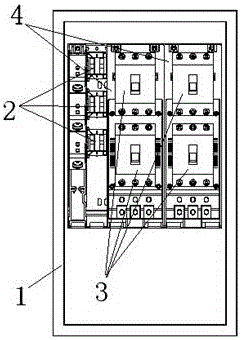
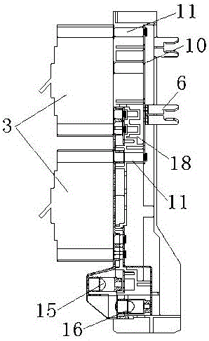
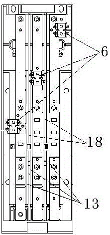
[0036] The accompanying drawings show an embodiment of the present invention. It can be seen from the accompanying drawings that the present invention relates to a multi-circuit breaker distribution cabinet or distribution box, including a cabinet 1, an incoming copper busbar 2 and a circuit breaker 3 , and four circuit breakers 3 are arranged in the box, which is characterized in that an adapter 4 is also provided in the box, and the four circuit breakers 3 are divided into two groups, and the two circuit breakers 3 in each group are arranged in two rows up and down The arrangement is installed on the adapter 4, and the four circuit breakers 3 are installed in the box body 1 through the adapter 4, and the incoming and outgoing lines of the four circuit breakers 3 are transferred through the adapter 4.

[0037] The four circuit breakers 3 are installed in the box body 1 through the adapter 4, that is, the adapter 4 is installed on the adapter mounting seat 5 together with the i...

Embodiment 2

[0047] The basic structure of the second embodiment is the same as that of the first embodiment, except that the way the adapter is connected to the incoming copper busbar is different. Plug, when the adapter is installed in the box, the plug-in socket of the adapter is inserted into the plug-in plug of the adapter mounting seat.


PUM


Abstract

A Multi-circuit-breaker power distribution cabinet or power distribution box comprises a box body, inlet wire copper busbars and circuit breakers. The plurality of circuit breakers are arranged on the box body. An adapter is arranged in the box body. The plurality of circuit breakers are installed on the adapter in up and down two rows. The plurality of circuit breakers are further installed in the box body through the adapter. Inlet and outlet wires of the plurality of circuit breakers are switched through the adapter. According to the invention, the plurality of circuit breakers are installed on the adapter in up and down two rows, two circuit breakers form one group, and the two circuit breakers in one group are installed on the adapter in an up-down combination manner. One plug-in type adapter is utilized to realize the up and down two-row arrangement of the plurality of circuit breakers, the transverse size of the power distribution cabinet (box) is substantially reduced, the hidden connection of the inlet and outlet wires is realized by the adapter, and no exposed copper wires can be seen from the appearance of the whole circuit breaker system, so that the installation degree is substantially improved, and the appearance after adaptation is more beautiful.

Description

technical field [0001] The invention relates to a power distribution system component device, in particular to a power distribution cabinet or distribution box with multiple circuit breakers, which is mainly used in the distribution box or power distribution cabinet where multiple circuit breakers need to be installed, and it is hoped that The working condition place that does not occupy space can also be used for the arrangement and combination of other electrical components in a distribution box or a distribution cabinet, and belongs to the technical field of power transmission and distribution equipment manufacturing. Background technique [0002] The power distribution cabinet (box) is a kind of power distribution system device widely used in our power transmission and distribution system. Generally, the power distribution cabinet (box) assembles switchgear, measuring instruments, protective appliances and auxiliary equipment in accordance with the requirements of electri...

Claims


Application Information

Patent Timeline
Patent Type & Authority Applications(China)
IPC IPC(8): H02B1/056H02B1/48H02B1/32
CPCH02B1/0565H02B1/32H02B1/48
Inventor 何志强张成林
Owner HUNAN HAOSHENG ELECTROMECHANICAL EQUIP
Learn More