Mobile crossing structure

A technology of engineering and works, which is applied in the field of movable crossing engineering works, can solve the problem of not allowing people or vehicles and water vehicles to pass at the same time

Inactive Publication Date: 2016-09-07
INGENI
View PDF7 Cites 10 Cited by
  • Summary
  • Abstract
  • Description
  • Claims
  • Application Information

AI Technical Summary

Problems solved by technology

The disadvantage of this system is that it does not allow p

Method used


Image

  • Mobile crossing structure
  • Mobile crossing structure
  • Mobile crossing structure

Examples


Embodiment Construction

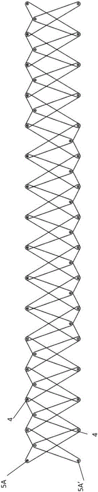
[0018] In one embodiment, a bridge connects two points separated by a waterway. The bridge comprises a deformable deck 1 extending between said two points.

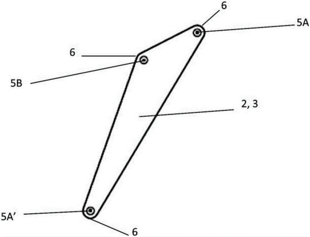
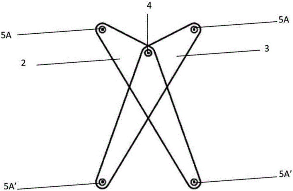
[0019] Such as figure 1 As shown in , the bridge comprises a set of generally triangular (scalene) elongated elements 2, 3 having three openings 5A, 5A', 5B at vertices 6 for receiving ball joints. A first opening 5A, 5A' is arranged at each end / vertex of the elements 2, 3, a second intermediate opening 5B is arranged between the two first openings 5A, 5A', the intermediate opening being formed by having the largest angle vertex representation. In the example shown, the maximum angle is about 140°, but could vary from 120° to 160° or even from 91° to 179°. The elements 2, 3 are flat and their thickness will depend on the material used. A ball joint is used to form the hinge 4 .

[0020] Each element 2, 3 consists of a first short portion between one first opening 5A and an intermediate opening 5B, and a second longer...


PUM


Abstract

A structure, which after construction is mobile and dynamic and connects two points separated by a natural or manmade obstacle, allows permanent crossing of this obstacle. The structure comprises a deformable deck (1) extending between said two points, a set of elements (2, 3), of elongate shape, having three openings (5A, 5A', 5B), a first opening (5A, 5A') at each end of the elements (2, 3) and an intermediate second opening (5B) positioned between the first two openings (5A, 5A') present at the ends of the elements (2, 3), said openings (5, 5A, 5A') accepting ball joints used to form hinges (4), each element (2, 3) being made up of a short first part between a first opening (5A) and the intermediate opening (5B) and of a longer second part between the other first opening (5A') and the intermediate opening (5B), the elements (2, 3) being arranged in pairs, with rotational mobility, about a central hinge (4) consisting of a ball in the intermediate openings (5B) of two elements (2, 3). An assembly of a number of pairs of elements (2, 3), which assembly is achieved using balls inserted into the openings (5A, 5A') arranged at the ends of each element (2, 3), is arranged along the deck (1), on one side or on both sides of the deck (1) in a plane substantially perpendicular to the axis of said hinges (4) and allowing relative movement of the elements (2, 3) from a first position towards a second position which movement takes place in said plane perpendicular to the axis of the hinges (4). Drive means (8) are positioned at one or both ends of said structure in order to adjust the length of the deck (1). The structure comprises drive means (8) arranged in such a way that when the means (8) come into action, they drive the assembly of pairs of elements (2, 3), said short parts of the elements (2, 3) being positioned on the upper part of the pairs of elements (2, 3) which are arranged at the ends of the structure while said short parts of the elements (2, 3) are arranged on the lower part of the pairs of elements (2, 3) which are arranged towards the centre of the structure so as to cause the central part of the deck (1) to adopt a dome shape when the means (8) are actuated.

Description

technical field [0001] The present invention relates to a movable traversing engineering work having a gradually changing shape by mechanical actuation. Background technique [0002] Generally, a work of engineering is a construction required to create and develop a communicating pathway, such as a bridge, tunnel or wall. In the case of a bridge, its structure allows traversing depressions or obstacles (watercourses, communicating channels, valleys, etc.) by passing over the separation created by said depressions or obstacles. Although the headroom of engineering works does not allow the combined passage of people and watercraft, when the passage of people and watercraft must exist simultaneously, the complexity of engineering works increases. [0003] There are some efforts that allow the intermittent passage of people or vehicles with watercraft. The main disadvantage of these efforts is that, when the watercraft crosses the bridge, it is necessary to interrupt the cross...

Claims


Application Information

Patent Timeline
IPC IPC(8): E01D15/12E01D15/20E04C3/00
CPCE01D6/00E01D15/02E01D15/124E01D15/20E04C3/005E01D15/12E01D19/04E01D15/24
Inventor E.布莱奥G.古斯塞蒂
Owner INGENI
Why Eureka
Try Eureka