
Optical method for monitoring plasma discharging glow

A discharge glow and optical monitoring technology, applied in the field of monitoring technology, can solve the problems of undeveloped plasma size and shape, and inability to know the plasma shape and absolute intensity.

Inactive Publication Date: 2016-09-14
CREATING NANO TECH INC
View PDF12 Cites 1 Cited by
  • Summary
  • Abstract
  • Description
  • Claims
  • Application Information

AI Technical Summary

Problems solved by technology

However, when grating spectrometer is used for detection, only the species and relative intensity of the plasma can be known, but the basic characteristics such as the shape and absolute intensity of the plasma cannot be known
[0003] Furthermore, no technology has been developed to correctly assess the size and shape of the plasma
Also, there is no technique for directly evaluating the intensity distribution of the plasma

Method used


Image

  • Optical method for monitoring plasma discharging glow
  • Optical method for monitoring plasma discharging glow

Examples


Embodiment Construction

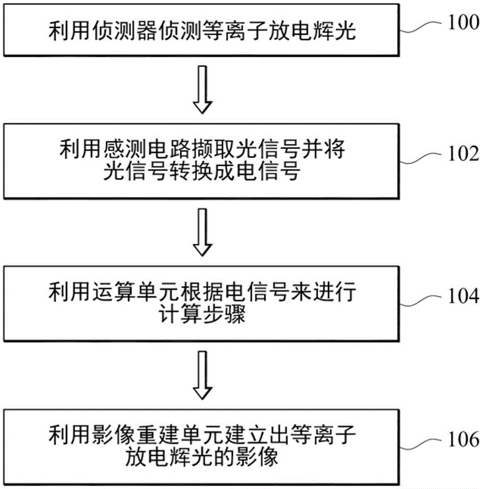
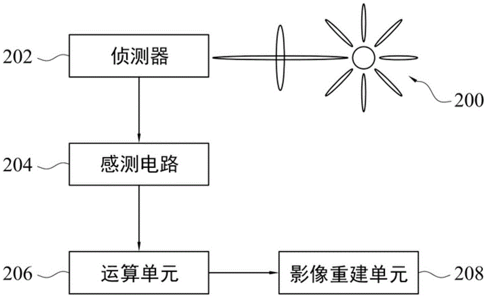
[0015] In view of the fact that there is currently no technology that can correctly evaluate the size and shape of the plasma, and there is no technology that can directly evaluate the intensity distribution of the plasma, so the present invention proposes an optical monitoring method for the plasma discharge glow, which uses an optical method. Detection of plasma discharge glow. Thereby, characteristics such as shape, size, temperature distribution, color distribution, flickering behavior, relative intensity, absolute intensity and intensity distribution of the plasma discharge glow can be evaluated effectively and quickly in a non-contact manner. Therefore, the efficacy of real-time monitoring of the plasma-treated area can be achieved. Moreover, since the present invention can use a charge-coupled device to detect the photoelectron intensity of the plasma discharge glow, the monitoring cost can be reduced.

[0016] Please also refer to figure 1 and figure 2 ,in figure ...


PUM


Abstract

An optical method for monitoring plasma discharging glow is described, which includes the following steps. Plasma discharging glow is detected to obtain various optical signals using a detector. The optical signals are captured and converted into various electric signals by using a sensing circuit. A calculation step is performed according to the electric signals to obtain various light intensities corresponding to various locations in the plasma discharging glow using an arithmetic unit. An image of the plasma discharging glow is reconstructed according to the locations in the plasma discharging glow and the corresponding light intensities using an image reconstruction unit. The optical method can effectively detect plasma discharging glow shapes, sizes, temperature distribution, color distribution and glowing action, and corresponding intensities, absolute intensities and intensity distribution, thereby obtaining the effect of instantly monitoring plasma processing areas.

Description

technical field [0001] The present invention relates to a monitoring technology, and in particular to an optical monitoring method of plasma discharge glow. Background technique [0002] The characteristics of the plasma generated by the plasma device can be used to evaluate the performance of the plasma device. In the analysis technology of plasma characteristics, grating spectrometer is mostly used to detect and analyze the plasma type at present. However, when the grating spectrometer is used for detection, only the species and relative intensity of the plasma can be known, but the basic characteristics such as the shape and absolute intensity of the plasma cannot be known. [0003] Furthermore, no technology has been developed to correctly assess the size and shape of the plasma. Furthermore, there is no technique for directly evaluating the intensity distribution of the plasma. Contents of the invention [0004] Therefore, an object of the present invention is to p...

Claims


Application Information

Patent Timeline
Patent Type & Authority Applications(China)
IPC IPC(8): G01N21/84G01N27/62
CPCG01N21/84G01N27/62G01J3/28G01J3/2803G01J3/443
Inventor 李志勇徐逸明王立民周昭旭黄友俊陈彦政
Owner CREATING NANO TECH INC
Learn More