Bearing ring shaping device and method

A bearing ring and shaping device technology, which is applied in the field of bearing manufacturing, can solve the problems of large wall thickness changes, difficulty in molding or mold deformation, complex structure, etc., and achieve high shaping efficiency, meet the needs of shaping, and be easy to operate.

Active Publication Date: 2016-09-21
AVIC HARBIN BEARING
View PDF5 Cites 11 Cited by
  • Summary
  • Abstract
  • Description
  • Claims
  • Application Information

AI Technical Summary

Problems solved by technology

[0004] In order to solve the problem that the bearing ring with complex structure and large wall thickness changes is difficult to realize the technology of molding or mold control deformation during the quenching process, the invention further proposes a bearing ring shaping device and method

Method used


Image

  • Bearing ring shaping device and method
  • Bearing ring shaping device and method
  • Bearing ring shaping device and method

Examples


specific Embodiment approach 1

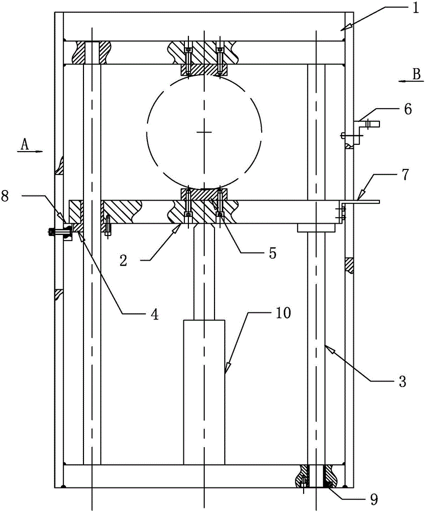
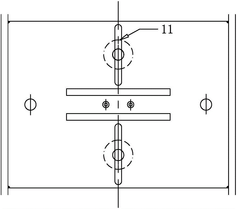
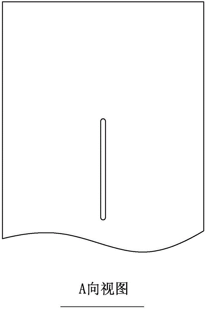
[0018] Specific implementation mode one: combine Figure 1 to Figure 4 Describe this embodiment, a bearing ring shaping device described in this embodiment includes a main body frame 1, a lifting beam 2, two guide columns 3, two guide sleeves 4, two fixed pads 5, an instrument seat 6, a positioning Platform 7, limit block 8, jack 10 and two adjustable columns 11, two guide columns 3 are installed vertically side by side in the main frame 1, and the upper ends of the two guide columns 3 are fixedly connected with the main frame 1, and the lifting The beam 2 is horizontally arranged in the main frame 1, and one end of the lifting beam 2 is slidably connected to a guide column 3 through a guide sleeve 4, and the other end of the lifting beam 2 is slidably connected to another guide column 3 through another guide sleeve 4, The jack 10 is arranged at the bottom in the main body frame 1, and the piston rod of the jack 10 is connected with the middle part of the lower surface of the ...

specific Embodiment approach 2

[0019] Specific implementation mode two: combination Figure 1 to Figure 4 To illustrate this embodiment, a bearing ring shaping device described in this embodiment also includes a positioning bolt 9 and a limit block 8, the limit block 8 is installed on the inner side wall of the main body frame 1 through the positioning bolt 9, and the limit block 8 is located below the lifting beam 2. Other components and connections are the same as those in the first embodiment.

specific Embodiment approach 3

[0020] Specific implementation mode three: combination Figure 1 to Figure 4 To illustrate this embodiment, the specific steps of a bearing ring shaping method described in this embodiment are as follows:

[0021] Step 1: Measure the ellipticity of the bearing ring 12 after quenching with an instrument, and mark the two points where the ellipse deformation of the bearing ring 12 is maximum;

[0022] Step 2, placing the marked bearing ring 12 between the two fixed blocks 5, and making the two points with the largest elliptical deformation of the bearing ring 12 contact with the surfaces of the two fixed blocks 5 respectively;

[0023] Step 3, drive the jack 10 to exert pressure on the maximum elliptical deformation of the bearing ring 12, and read out the size of the plastic size through the measuring instrument arranged on the instrument base 6 during the force application process;

[0024] Step 4: After the shaping is completed, the bearing ring 12 is removed from between th...


PUM


Abstract

The invention relates to a shaping device and method, and particularly relates to a bearing ring shaping device and method. The bearing ring shaping device and method aim at solving the problem that a molding pressing technology or a mold control deformation technology is difficult to realize in a quenching process of a bearing ring which is complicated in structure and changes greatly in wall thickness. The bearing ring shaping device comprises a main body frame, a lifting cross beam, two guide columns, two guide sleeves, two fixing cushion blocks, an instrument pedestal, a positioning table, a limited block, a jack and two adjustable vertical columns, wherein the two guide columns are vertically arranged in the main body frame side by side; the upper ends of the two guide columns are fixedly connected to the main body frame; and the lifting cross beam is horizontally arranged in the main body frame. The bearing ring shaping device and method belong to the field of bearing manufacturing.

Description

technical field [0001] The invention relates to a shaping device and method, in particular to a bearing ring shaping device and method, belonging to the field of bearing manufacturing. Background technique [0002] The heat treatment deformation of the bearing ring has a great influence on the product quality. Although it can be corrected through the heat treatment process, the shaping technology is also one of the effective measures to control the deformation. The structure of SG13Cr4Mo4Ni4V steel bearing ring is complex, and the wall thickness changes greatly. The quenching and tempering treatment of the ring after carburizing is all completed in a vacuum air quenching furnace. , It is difficult to realize molding or mold control deformation technology in the quenching process, and the ferrule shaping can only be achieved by rectifying or shaping methods before tempering, through martensite transformation and residual austenite transformation in the tempering process, to a...

Claims


Application Information

Patent Timeline
Patent Type & Authority Applications(China)
IPC IPC(8): B21D3/16B21D53/10
CPCB21D3/16B21D53/10
Inventor 刘秀莲刘明安敏吴玉成班君罗燕袁超吕钟毓周淑梅
Owner AVIC HARBIN BEARING
Why Eureka
Try Eureka