Vacuum claw type rubber tube sleeving device

A rubber tube and claw-type technology, which is applied in the field of vacuum claw-type rubber tube fitting devices, can solve the problems that soft rubber tubes are not easy to fit, and achieve the effect of good fitting and increasing the fit gap

Active Publication Date: 2016-09-21
SHANGHAI YIBOW SHIPPING CO LTD
View PDF7 Cites 2 Cited by
  • Summary
  • Abstract
  • Description
  • Claims
  • Application Information

AI Technical Summary

Problems solved by technology

[0013] The purpose of the present invention is to overcome the above-mentioned defects in the prior art, and provide a vacuum claw type rubber tube fitting device to solve the problem that the soft rubber tubes are not easy to fit when making the rubber filling layer of the elastic seal of the cable penetration device. question

Method used


Image

  • Vacuum claw type rubber tube sleeving device
  • Vacuum claw type rubber tube sleeving device
  • Vacuum claw type rubber tube sleeving device

Examples


Embodiment Construction

[0035] The specific embodiment of the present invention will be further described in detail below in conjunction with the accompanying drawings.

[0036] It should be noted that, in the following specific embodiments, when describing the embodiments of the present invention in detail, in order to clearly show the structure of the present invention for the convenience of description, the structures in the drawings are not drawn according to the general scale, and are drawn Partial magnification, deformation and simplification are included, therefore, it should be avoided to be interpreted as a limitation of the present invention.

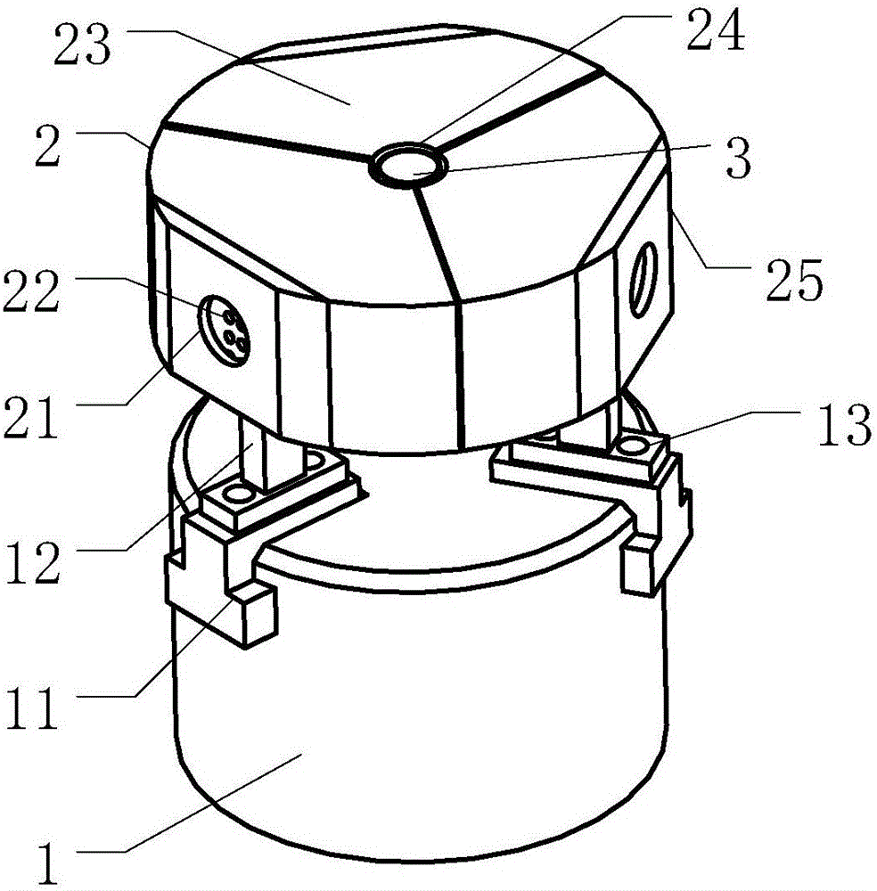
[0037] In the following specific embodiments of the present invention, please refer to image 3 , image 3 It is a structural schematic diagram of a vacuum claw-type rubber tube fitting device in a preferred embodiment of the present invention. Such as image 3 As shown, a vacuum claw-type rubber tube fitting device of the present invention includ...


PUM


Abstract

The invention discloses a vacuum claw type rubber tube sleeving device. An opening hole is formed in the spliced center of multiple opening claws, and a vacuum cavity is formed by forming a vacuumizing air hole in the side wall of the opening hole, so that the pipe wall of a first to-be-sleeved rubber tube placed in the opening hole can be evenly sucked to the side wall of the opening hole. The opening claws are driven to expand to evenly expand the sucked first rubber tube outwards, so that the fit clearance between an inner rubber tube and an outer rubber tube is increased, a second rubber tube can be smoothly put into the first rubber tube, and finally the first rubber tube is separated from the side wall of the opening hole and restored by stopping vacuumizing operation. Accordingly, the inner rubber tube and the outer rubber tube are well sleeved. Multi-layer sleeving of rubber tubes with different diameters can be conducted conveniently and rapidly through the device.

Description

technical field [0001] The invention relates to the technical field of cable penetrating seal installation, and more specifically, to a vacuum claw-type rubber tube fitting device. Background technique [0002] In ships and offshore drilling platforms, openings are often required in structures such as cabins, walls or partitions to penetrate cables / wires. In order to seal and protect the cables from fire, smoke, gas and water, etc., at these openings, cable penetrations are used. [0003] see figure 1 , figure 1 It is a schematic diagram of the outline structure of an existing cable penetration device. Such as figure 1 As shown, the existing cable penetration device generally includes a rigid frame 100, the frame is pre-embedded on the partition or wall, and multiple groups of elastic seals 200 for clamping the cables 300 passing through the frame are installed in the frame, and , a compression block 400 for expanding between the inner wall of the frame and the elastic ...

Claims


Application Information

Patent Timeline
Patent Type & Authority Applications(China)
IPC IPC(8): B25B27/00
CPCB25B27/00
Inventor 张东升
Owner SHANGHAI YIBOW SHIPPING CO LTD
Why Eureka
Try Eureka