A combined adjusting pin shaft

A technology for adjusting pins and tapered surfaces, applied to pins, connecting components, mechanical equipment, etc., can solve the problems of increasing the frictional resistance of the pin shaft, large equipment damage, and long maintenance period, so as to increase the matching clearance and facilitate disassembly. , The effect of reducing the disassembly resistance

Active Publication Date: 2016-06-29
CHINA NAT HEAVY MACHINERY RES INSTCO
View PDF9 Cites 0 Cited by
  • Summary
  • Abstract
  • Description
  • Claims
  • Application Information

AI Technical Summary

Problems solved by technology

[0002] In the sector structure clamped by the connecting rod pin shaft, after a period of operation of the equipment, it is very difficult to disassemble the pin shaft. Users often use the destruction method of oxygen lance blowing and cutting. The maintenance period is long and the equipment damage is large, which is not conducive to Maintenance and repair of continuous casting equipment
There are two main factors that cause the pin shaft to be difficult to disassemble. On the one hand, some rust is caused by high-temperature steam and mold slag. These rusts and other dust accumulate to prevent the pin shaft from being pulled out.
On the other hand, the pre-clamping force of the clamping mechanism of the segment or the downforce generated by the self-weight of the upper frame makes the pin shaft have a pulling force during the disassembly stage, which increases the frictional resistance of the pin shaft pulling out

Method used


Image

  • A combined adjusting pin shaft
  • A combined adjusting pin shaft

Examples


Embodiment Construction

[0010] The present invention is described in detail below in conjunction with accompanying drawing.

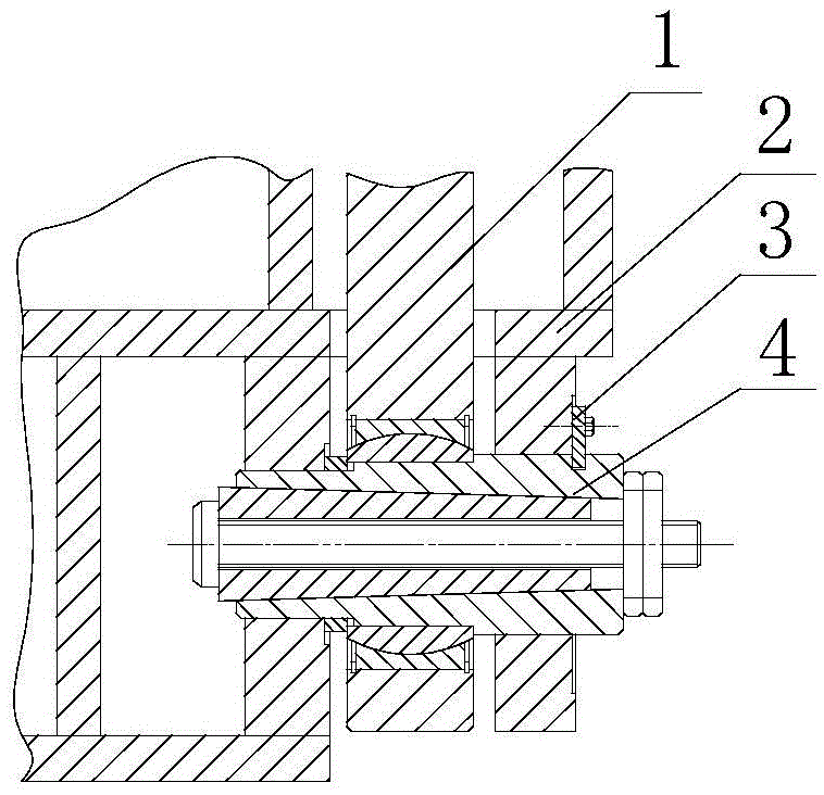
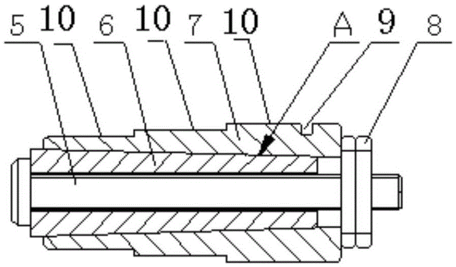
[0011] refer to figure 1 , figure 2 , a combined adjustment pin shaft, including an outer shaft 7, the outer surface of the outer shaft 7 is provided with a positioning step 10, the outer shaft 7 is designed with a matching step and a shaft diameter with different matching requirements according to the matching requirements of the pin shaft, the outer shaft 7 and the inner shaft The 6 are radially matched through the tapered surface A, and the outer shaft 7 is longitudinally opened with a groove 9 with a width of 2-4mm. The other end is screwed with the nut 8, and the left end surface of the nut 8 is close to the small end surface of the tapered surface of the outer shaft 7.

[0012] Working principle of the present invention is:

[0013] refer to figure 1 , the combined pin shaft 4 of the present invention, the joint bearing on the connecting rod 1 and the sector frame 2...


PUM


Abstract

A combined regulation pin shaft comprises an outer shaft; positioning steps are arranged at the outer surface of the outer shaft; the outer shaft and an inner shaft are radially matched by a conical surface A; a groove being 2-4mm wide is formed along the longitudinal direction of the outer shaft; a pull rod is inserted in the inner shaft and the head of the pull rod is at the large end part of the conical surface of the inner shaft; the other end of the pull rod is rotationally combined with a nut 8; the left end surface of the nut is abutted against the end surface of the small end of the outer shaft; when the nut is axially tensioned, the outer shaft and the inner shaft relatively slide along the matched conical surface, so the outer shaft is expanded and an outer ring of the outer shaft is expanded, the match precision demand of the outer ring of a pin shaft, a sector section frame and a connection rod bearing is met, and the function need for realizing the fast and precise match between the radial direction and the axial direction is realized; during disassembly, the pull rod is loosened, the inner shaft is knocked to be pushed along the conical surface, the outer diameter of the outer shaft is reduced due to the reduction or removal of the expanding action force of the inner shaft, the match gap between the outer shaft and a match part is increased, the disassembly resistance of the pin shaft is reduced and the pin shaft is convenient to disassemble. The maintenance strength is reduced, the mounting or dismounting efficiency of the pin shaft is enhanced and the service life of the pin shaft is prolonged.

Description

technical field [0001] The invention relates to the technical field of continuous casting in the metallurgical industry, and can also be applied to other mechanical equipment fields, in particular to a combined adjusting pin researched and developed to solve the difficulty of installing and dismounting the pin shafts of continuous casting sectors. Background technique [0002] In the sector structure clamped by the connecting rod pin shaft, after a period of operation of the equipment, it is very difficult to disassemble the pin shaft. Users often use the destruction method of oxygen lance blowing and cutting. The maintenance period is long and the equipment damage is large, which is not conducive to Maintenance and repair of continuous casting equipment. There are two main factors that cause the pin shaft to be difficult to disassemble. On the one hand, some rust is caused by high temperature steam and mold slag, and these rust spots and other dust accumulate to prevent the...

Claims


Application Information

Patent Timeline
Patent Type & Authority Patents(China)
IPC IPC(8): F16B13/06
Inventor 杨拉道雷华刘赵卫
Owner CHINA NAT HEAVY MACHINERY RES INSTCO
Why Eureka
Try Eureka