
Center-of-gravity self-regulated self-balancing unicycle

A self-adjusting, unicycle technology, applied to foldable bicycles, bicycles, motor vehicles, etc., can solve the problems of unstable center of gravity, unsafety, falling, etc., and achieve the effect of improving safety, convenient use, and reducing force

Inactive Publication Date: 2016-09-21
李陈
View PDF5 Cites 0 Cited by
  • Summary
  • Abstract
  • Description
  • Claims
  • Application Information

AI Technical Summary

Problems solved by technology

The rise of self-balancing electric unicycles is about to trigger a new traffic revolution; when riding an existing electric unicycle, the user can control the forward or brake of the unicycle by adjusting the body forward or backward, and when riding at a faster speed When an emergency brake is required during walking, the user will subconsciously lean back the body to brake the unicycle as soon as possible. Excessive force on the motor of the unicycle will cause the instantaneous current to be too large, which will affect the service life of the motor

Method used


Image

  • Center-of-gravity self-regulated self-balancing unicycle
  • Center-of-gravity self-regulated self-balancing unicycle
  • Center-of-gravity self-regulated self-balancing unicycle

Examples


Embodiment 1

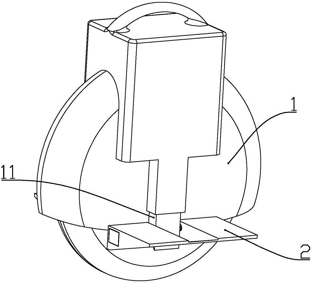
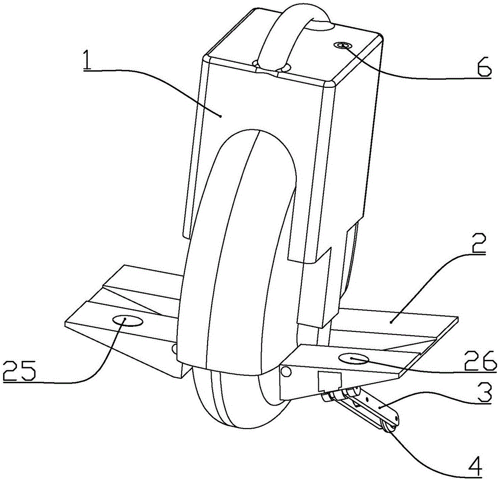
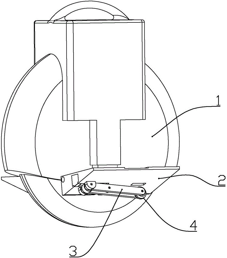
[0021] according to figure 1 and Figure 7 As shown, a self-balancing unicycle with an automatic center of gravity adjustment described in this embodiment includes a car body 1 and two pedals 2 installed on the mounting columns 11 on both sides of the car body, and the bottom of one or two of the pedals The auxiliary wheel system is installed on the surface; the auxiliary wheel system includes an auxiliary wheel 4, a support rod 3 for installing the auxiliary wheel, a mounting seat 20 formed under the pedal and connected to the support rod in rotation, and a support The driving rod 5 connected in rotation at the middle part of the rod, and a slider 7 connected in rotation with the other end of the driving rod, a slide rail 22 for sliding the slider is formed inside the pedal, and electromagnetic Iron A91 and electromagnet B92, the electromagnet B is close to the middle of the pedal relative to the electromagnet A; two permanent magnets (not shown in the figure) are installed ...

Embodiment 2

[0031] A self-balancing unicycle with an automatic center of gravity adjustment described in this embodiment includes a car body 1 and two pedals 2 installed on the mounting columns 11 on both sides of the car body, one or two of which are An auxiliary wheel system is installed on the lower surface of the pedal; the auxiliary wheel system includes an auxiliary wheel 4, a support rod 3 for installing the auxiliary wheel, and a mounting seat 20 formed under the pedal and rotatably connected with the support rod , a drive rod 5 that is rotatably connected to the middle part of the support rod, and a slider 7 that is rotatably connected to the other end of the drive rod. A slide rail 22 for sliding the slider is formed in the pedal, and the two ends of the slide rail are respectively An electromagnet A91 and an electromagnet B92 are installed, and the electromagnet B is close to the middle of the pedal relative to the electromagnet A; two permanent magnets (not shown) are installed...


PUM


Abstract

The invention discloses a center-of-gravity self-regulated self-balancing unicycle comprising a body and two pedals mounted on mounting columns on two sides of the body. A screw rod is rotationally connected on each pedal, a motor for driving the corresponding screw rod to rotate is mounted in each pedal, and each screw rod is connected with the corresponding mounting column in a screw driving manner; each motor is electrically connected with a controller of the unicycle. When the unicycle runs fast, the motors drive the screw rods to rotate reversely so as to enable the pedals to move backwards towards the running direction of the unicycle, therefore, when braking is required, a user only needs to lean slightly back, then the center of gravity moves to the back of the unicycle at once, and the unicycle can be braked in time and ensures that the user cannot fall down because of leaning back too much.

Description

[0001] This patent is: [0002] The name of the invention is: a self-balancing unicycle with automatic center of gravity adjustment [0003] The application number is: 2014108262661 [0004] The application date is: 2014.12.25 [0005] divisional application of the patent application. technical field [0006] The invention belongs to the field of unicycle structures, and in particular relates to a self-balancing unicycle with an automatic center of gravity adjustment. Background technique [0007] Self-balancing electric unicycle is a means of transportation with electric drive and self-balancing function. With the rapid development of society today, traffic congestion has become a common phenomenon. Electric unicycles replace bicycles and electric vehicles as transportation tools. The rise of self-balancing electric unicycles is about to trigger a new traffic revolution; when riding an existing electric unicycle, the user can control the forward or brake of the unicycle ...

Claims


Application Information

Patent Timeline
Patent Type & Authority Applications(China)
IPC IPC(8): B62K3/00B62K15/00
CPCB62H1/12B62K1/00B62K11/00B62K15/00
Inventor 李陈
Owner 李陈
Learn More