An automatic jaw clutch

A jaw clutch and clutch technology, applied in the field of clutches, can solve problems such as complex spindle fixing methods, high friction of power ratchets, and increased cost of use, and achieve the effects of simple structure, reduced friction, and easy operation

Inactive Publication Date: 2018-06-22
NINGBO UNIVERSITY OF TECHNOLOGY
View PDF6 Cites 0 Cited by
  • Summary
  • Abstract
  • Description
  • Claims
  • Application Information

AI Technical Summary

Problems solved by technology

[0003] With this structure, the fixing method of the main shaft is complicated, and the friction between the main shaft and the sprocket flange and the power ratchet is relatively large
In the long-term use process, the wear and tear between the parts is relatively serious, the service life is too short, and the parts need to be replaced frequently, resulting in an increase in the cost of use

Method used


Image

  • An automatic jaw clutch
  • An automatic jaw clutch
  • An automatic jaw clutch

Examples


Embodiment Construction

[0029] The principles and features of the present invention are described below in conjunction with the accompanying drawings, and the examples given are only used to explain the present invention, and are not intended to limit the scope of the present invention.

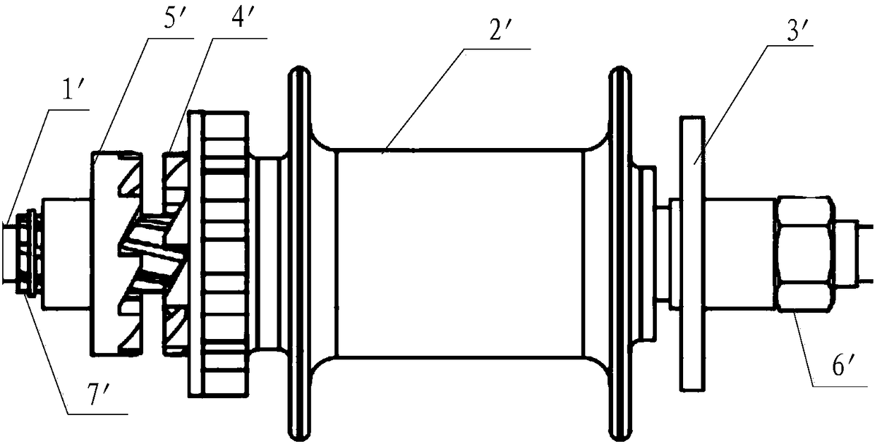
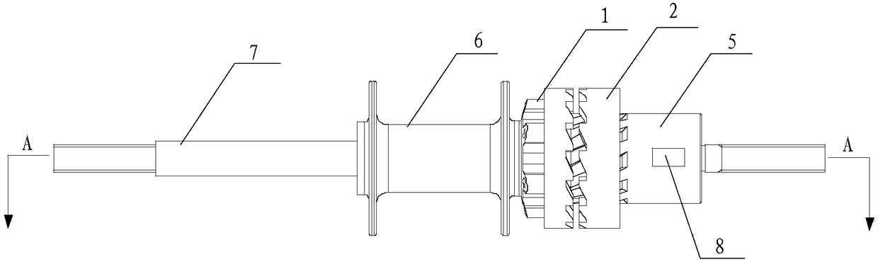
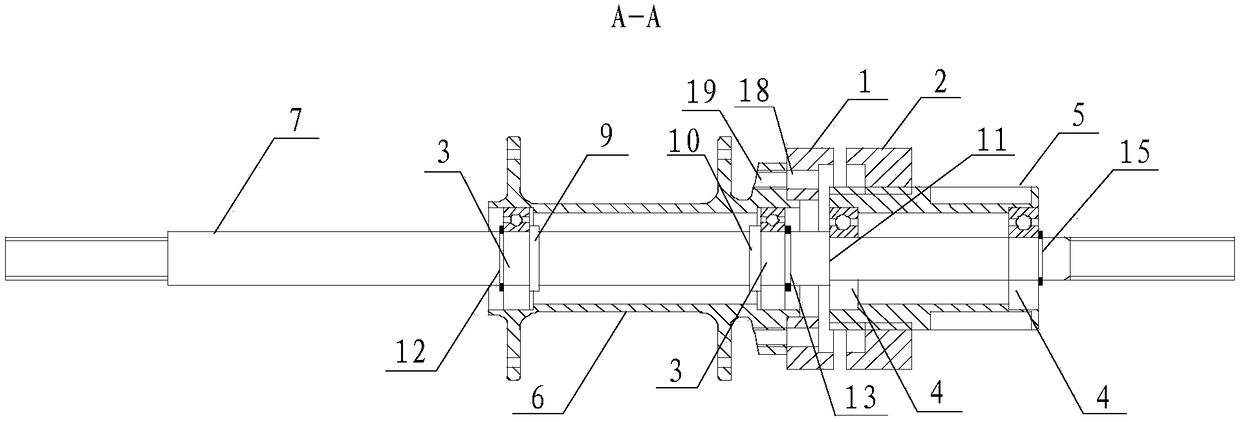
[0030] Such as Figure 2-3 Shown, a kind of automatic jaw clutch, it comprises first half clutch 1, second half clutch 2, first bearing 3, second bearing 4, spline sleeve 5, hub 6 and axle 7, described axle 7 is an elongated cylindrical shaft; the hub 6 is sleeved on the hub 7, and the two ends of the hub 6 are rotationally connected to the hub 7 through the first bearing 3; the first One end of the half-clutch 1 is provided with passive teeth, and the other end is fixedly connected with the hub 6; the spline sleeve 5 is sleeved on the wheel shaft 7, and the two ends of the spline sleeve 5 respectively pass through the The second bearing 4 is rotatably connected with the wheel shaft 7, the spline sleeve 5 is close ...


PUM


Abstract

The invention relates to an automatic tooth-embedded clutch. The automatic tooth-embedded clutch comprises a first half clutch body, a second half clutch body, first bearings, second bearings, a spline sleeve, a spline drum and a wheel shaft. The wheel shaft is a long strip-shaped cylindrical shaft. The two ends of the spline drum are both rotatably connected with the wheel shaft through the first bearings. Driven teeth are arranged at one end of the first half clutch body, and the other end of the first half clutch body is fixedly connected with the spline drum. The two ends of the spline sleeve are both rotatably connected with the wheel shaft through the second bearings. The spline sleeve is close to the first half clutch body. A key groove matched with a chain wheel is formed in the outer side of the spline sleeve. The second spline sleeve is sleeved with the second half clutch body. Driving teeth are arranged at the end, close to the first half clutch body, of the second half clutch body. The second half clutch body can be driven by the spline sleeve to rotate, and the second half clutch body can move on the spline sleeve to be close to or away from the first half clutch body. According to the technical scheme, on the basis that automatic separation and combination of the clutch can be achieved, the wheel shaft is fixedly arranged, friction between the wheel shaft and rotary components is reduced, and the fixing way of the wheel shaft is simplified.

Description

technical field [0001] The invention relates to the technical field of a clutch, in particular to an automatic jaw clutch. Background technique [0002] Such as figure 1 As shown, the existing main shaft 1' with its own jaw clutch can rotate under the drive of the sprocket flange 3', and the sprocket flange 3' is fixedly connected to the main shaft 1' through the flange nut 6'. The hub ratchet 4' is fixedly connected with the hub 2', the power ratchet 5' cooperates with the main shaft 1' through a helical spline, and the ratchet stop ring 7' blocks and limits the power ratchet 5'. During the specific clutch process, the sprocket flange 3' drives the main shaft 1' to rotate through the spline, and the rotating spline on the main shaft 1' drives the power ratchet 5' to rotate. When the rotation speed of the power ratchet 5' is lower than that of the main shaft 1' When the rotational speed of the main shaft 1' is guided by the rotating spline, the power ratchet 5' closes with...

Claims


Application Information

Patent Timeline
Patent Type & Authority Patents(China)
IPC IPC(8): F16D43/04
CPCF16D43/04
Inventor 姚喜贵王汝旷包梦阳顾晗蔡琛辉
Owner NINGBO UNIVERSITY OF TECHNOLOGY
Why Eureka
Try Eureka