
Dish washer body component

A technology for dishwashers and components, which is applied to parts of tableware washing machines/rinsing and washing machines, tableware washing machines/rinsing machines, cleaning equipment, etc., and can solve problems such as many washing dead ends, high cost, and poor washing effect

Inactive Publication Date: 2016-09-28
SHENGZHOU HAIYUSI ELECTRICAL APPLIANCE CO LTD
View PDF7 Cites 10 Cited by
  • Summary
  • Abstract
  • Description
  • Claims
  • Application Information

AI Technical Summary

Problems solved by technology

[0003] The present invention aims to solve the problems of many washing dead spots, poor washing effect, and high cost in the prior art dishwasher, and provides a main component of the dishwasher according to the present invention. Fast speed, simple structure and low cost

Method used


Image

  • Dish washer body component
  • Dish washer body component
  • Dish washer body component

Examples


Embodiment 1

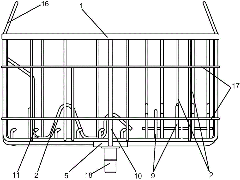
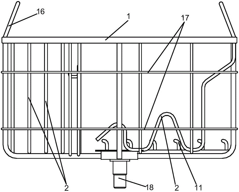
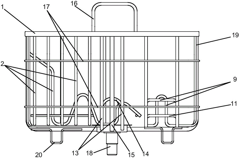
[0042] A main component of a dishwasher, which has a frame body, an upper frame 1 made of pipe sections is connected to the frame body, and the upper frame 1 is composed of a left frame part 1-1, a rear frame part 1-2, a right frame part 1-3 and The front frame part 1-4 is surrounded into a chamfered rectangular shape, and there are a number of through holes 1-5 sealed with the corresponding nozzles under the upper frame 1, and there are handles 16 on the left and right sides of the upper frame. The bottom is provided with a water inlet chamber 5, which is connected with a water inlet interface 18 below the water inlet chamber. Pipe B4, main through pipe C8, main through pipe D10, the upper bend sections of main through pipe A, main through pipe B, main through pipe C and main through pipe D are respectively sealed and connected to the left frame part 1-1 of the upper frame 1 , the rear frame part 1-2, the right frame part 1-3, the through hole 1-5 provided below the front fra...

Embodiment 2

[0048] This example differs from the previous example in that the rack is a rotary spray rack 23, which replaces the corrugated tube rack in the previous example. The rotary spray rack 23 in this example has an asymmetrical U-shaped water-through support pipe 231, the upper end of the short limb of the asymmetric U-shaped water-through support pipe is pivotally connected with a pivoted arm 232 through a pin shaft 233 connected in the horizontal direction. The water spray hole 23212 is provided with a cover plate 2322 behind the substrate, and the long limb of the asymmetrical U-shaped water-through support pipe extends upwards and is sealed to the through hole below the upper frame.

[0049] The pressurized hot water is input from the water inlet port 18, reaches the water inlet chamber 5, enters the upper frame 1 through the main pipe A15, the main pipe B4, the main pipe C8, and the main pipe D10, and then flows through the asymmetrical U-shaped The long limb of the support p...

Embodiment 3

[0051] This example differs from Example 1 in that the rack is a shower spray rack 25, replacing the corrugated tube rack in Example 1. The shower spray rack in this example has an L-shaped water-through support pipe 251 The horizontal section of the L-shaped water-passing support pipe is connected with a basin-shaped spray cover 252, and the front of the basin-shaped spray cover is provided with the spray hole, and the vertical section of the L-shaped water-passing support pipe extends upwards and is connected to the above-mentioned via holes below the box.

[0052] The pressurized hot water is input from the water inlet port 18, reaches the water inlet chamber 5, enters the upper frame 1 through the main through pipe A15, the main through pipe B4, the main through pipe C8, and the main through pipe D10, and then flows through the L-shaped water support pipe The vertical section of 251 enters, reaches basin shape spray cover 252, then sprays from the spray hole of basin shape...


PUM


Abstract

The invention provides a dish washer body component which is simple in structure, low in cost and good in washing effect. An upper frame made of pipe sections is arranged on a frame body. A plurality of dish racks and plate racks are arranged in the frame body. A water inlet cavity is formed in the bottom of the frame body. The lower face of the water inlet cavity is connected with a water inlet connector. The left side, the rear side, the right side and the front side of the water inlet cavity are communicated with a main through pipe A, a main through pipe B, a main through pipe C and a main through pipe D which are bent upwards after flat extending respectively. The upwards-bent sections of the main through pipe A, the main through pipe B, the main through pipe C and the main through pipe D are sealed and connected to through holes in the lower face of the upper frame. Dish rack fixing pipes are arranged at the bottom of the frame body. The dish rack fixing pipes are bent upwards after being flat arranged and are then sealed and connected to through holes in the lower face of the upper frame. The dish racks are bridge span type dish racks made of pipe sections. The two ports of the lower portions of the dish racks are sealed and connected to through holes in the upper faces of the dish rack fixing pipes. The ends, in the water inlet direction, of the plate racks are connected to the lower face of the upper frame and communicated with through holes in the lower face of the upper frame. The bottoms of the plate racks are connected with plate rack fixing ribs. The dish racks and the plate racks are provided with water spraying holes. The dish washer body component is used for washing tableware.

Description

technical field [0001] The invention relates to a dishwasher, in particular to a main structural component of the dishwasher. Background technique [0002] Social progress and rapid economic development have greatly accelerated the pace of people's work and life. The development of home appliances and civilian purchases have brought a lot of convenience to the daily life of modern families. Dishwashers have been gradually popularized in households to replace people's tedious and time-consuming tableware washing tasks. There are many brands and types of dishwashers in the prior art, and Siemens, Oaks, Haier, Fotile, etc. have successively launched various types of dishwashers. Most of the dishwashers in the prior art clean tableware by spiral spraying. The existing problems are that the effect is limited due to mechanical regularity, there are many dead spots in the washing area, and most domestic households are used to cooking with too much oil. , leading to even less opt...

Claims


Application Information

Patent Timeline
IPC IPC(8): A47L15/16A47L15/22A47L15/42A47L15/50
CPCA47L15/22A47L15/16A47L15/4214A47L15/4278A47L15/428A47L15/502A47L15/505A47L2601/02
Inventor 赵绍舟郑士元崔伯仁
Owner SHENGZHOU HAIYUSI ELECTRICAL APPLIANCE CO LTD
Learn More