Novel scutcher

A cotton cleaning machine and cotton cleaning technology, which can be applied to fiber cleaning machines, fiber cleaning, and tooth-shaped tools for cleaning, etc., which can solve the problems of wasting manpower and material resources, entangled in acupuncture, and unsatisfactory function of the cleaning machine. , to achieve a sufficient degree of increase and decrease, and improve the quality of the effect

Active Publication Date: 2016-09-28
WANGJIANG RUNHUA TEXTILE
View PDF7 Cites 9 Cited by
  • Summary
  • Abstract
  • Description
  • Claims
  • Application Information

AI Technical Summary

Problems solved by technology

[0002] Existing cleaning machines usually include a beating roller for breaking up the cotton bales. The beating roller has needles. After the machine is started, the beating roller starts to rotate, and the needles can disassemble the cotton bales and turn them into cotton bundles; The negative pressure equipment pulls out the cotton bundles, stores them in the cotton storage box, and cleans up the impurities, useless short cotton wool and dust in the cotton bales. However, most enterprises currently use the cleaning machine’s unsatisfactory functions. When the bales are disassembled into cotton bundles, they come out of the cleaning machine with a lot of useless cotton wool and dust, or some impurities that cannot be cleaned up. This has led some companies to divide the dismantling, impurity removal and dust removal of cotton bales into three parts. It is a serious waste of manpower and material resources to operate in two steps, and there are still situations in which the cotton bundles are often entangled on the needles during the working process of the cotton cleaning machine. When the cotton bundles wound on the needles reach a certain level, the working efficiency of the cotton cleaning machine will decrease. will reduce

Method used


Image

  • Novel scutcher

Examples


Embodiment Construction

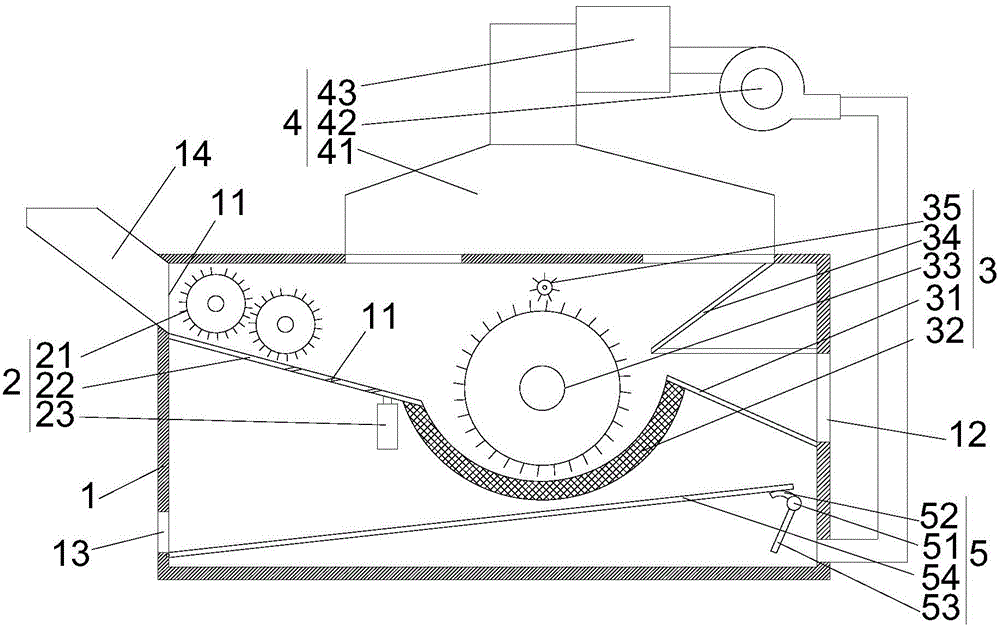
[0017] refer to figure 1 As shown, a new type of cleaning machine proposed by the present invention includes a cleaning box 1, an initial cleaning mechanism 2, a fine cleaning mechanism 3, a dust removal mechanism 4 and a miscellaneous guide mechanism 5;

[0018] One side of the cleaning box 1 is provided with a feed port 11, and the side of the cleaning box 1 away from the feed port 11 is provided with a discharge port 12, and the cleaning box 1 is provided with a miscellaneous port 13, which is connected to the feed port 13 The port 11 is located on the same side of the cleaning box 1 and the miscellaneous outlet 13 is located below the feeding port 11, and the cleaning box 1 is provided with a feeding pipe 14 corresponding to the feeding port 11.

[0019] The initial cleaning mechanism 2 includes at least two small beater rollers 21, a cotton guide plate 22 and a vibrating motor 23; the small beater roller 21 is provided with acupuncture, and the cotton guide plate 22 is ob...


PUM


Abstract

The invention provides a novel scutcher. The novel scutcher comprises a scutching box, an initial scutching mechanism, a fine scutching mechanism and a dust removal mechanism. A feed port, a discharge port and an impurity output opening are formed in one side of the scutching box. The initial scutching mechanism comprises at least two small hitting rollers and a cotton guide plate. Prods are arranged on the small hitting rollers. The cotton guide plate is obliquely installed in the scutching box. Multiple impurity guide holes are obliquely formed in the cotton guide plate. The fine scutching mechanism comprises a cotton output plate, a dust removal knife, a large hitting roller and a cotton return plate. A prod is arranged on the large hitting roller. The dust removal mechanism comprises a dust removal cover, a dust removal box and a draught fan. The dust removal cover is communicated with the upper end of the scutching box. The communicating positions of the dust removal cover and the scutching box are located on the two sides of the large hitting roller, the dust removal cover is in pipeline communication with the dust removal box, the dust removal box is in pipeline communication with an air inlet of the draught fan, an outlet of the draught fan is communicated with the scutching box, and the communicating position of the air outlet of the draught fan and the scutching box and the discharge port are located in the same side of the scutching box, and the communicating position is located below the discharge port. Cotton bales can be efficiently subjected to disassembly, impurity removal and dust removal.

Description

technical field [0001] The invention relates to textile machinery, in particular to a novel cotton cleaning machine. Background technique [0002] Existing cleaning machines usually include a beating roller for breaking up the cotton bales. The beating roller has needles. After the machine is started, the beating roller starts to rotate, and the needles can disassemble the cotton bales and turn them into cotton bundles; The negative pressure equipment pulls out the cotton bundles, stores them in the cotton storage box, and cleans up the impurities, useless short cotton wool and dust in the cotton bales. However, most enterprises currently use the cleaning machine’s unsatisfactory functions. When the bales are disassembled into cotton bundles, they come out of the cleaning machine with a lot of useless cotton wool and dust, or some impurities that cannot be cleaned up. This has led some companies to divide the dismantling, impurity removal and dust removal of cotton bales int...

Claims


Application Information

Patent Timeline
Patent Type & Authority Applications(China)
IPC IPC(8): D01G9/00D01G9/06D01G9/14
CPCD01G9/00D01G9/06D01G9/14
Inventor 胡文才
Owner WANGJIANG RUNHUA TEXTILE
Why Eureka
Try Eureka