
Measuring device and measuring method for optical material loss

An optical material and measurement device technology, applied in the field of optical measurement, to achieve the effects of suppressing noise, improving signal-to-noise ratio, and increasing loss

Active Publication Date: 2016-09-28
SHANGHAI INST OF OPTICS & FINE MECHANICS CHINESE ACAD OF SCI
View PDF6 Cites 1 Cited by
  • Summary
  • Abstract
  • Description
  • Claims
  • Application Information

AI Technical Summary

Problems solved by technology

Improve measurement accuracy by eliminating the effects of beam offset and surface defects during measurement

Method used


Image

  • Measuring device and measuring method for optical material loss
  • Measuring device and measuring method for optical material loss

Examples


Embodiment Construction

[0028] The present invention will be further described below in conjunction with example and accompanying drawing, but should not limit protection scope of the present invention with this.

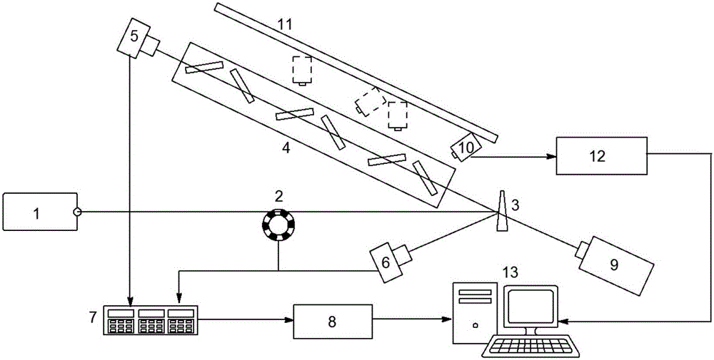
[0029] see first figure 1 , figure 1 It is a schematic diagram of the optical material loss testing device of the present invention. As can be seen from the figure, a measuring device for optical material loss is characterized in that its composition includes:

[0030] A solid-state laser 1, along the laser output direction of the solid-state laser 1 are a chopper 2 and a beam splitter 3 in sequence, and the beam splitter 3 divides the laser beam emitted by the solid-state laser 1 into a measurement beam and a reference beam. The direction of the measuring beam is followed by the first optical platform 4 and the first photodetector 5, and the second photodetector 6 is set in the direction of the reference beam, the output end of the first photodetector 5, the second photodetector The out...


PUM


Abstract

The invention discloses a measuring device and a measuring method for optical material loss. Influences of surface loss are removed by measuring transmittance difference, at the same angle of incidence, of sample groups only with different thicknesses, so that material loss of samples is obtained. During measuring, measuring precision is improved by eliminating beam deviation and surface defect influences. Measuring precision of material loss is further improved by increasing group number of samples, improving integral loss amount, utilizing a phase-lock amplifying technology to inhibit noises and increasing a signal-to-noise ratio. The device and the method have the characteristics of being simple in structure, convenient to regulate and relatively high in precision.

Description

technical field [0001] The invention relates to optical measurement, in particular to an optical material loss measurement device and measurement method. Background technique [0002] In high-power laser devices, the loss of optical components formed by various optical materials not only affects the maximum output energy of the laser, but also affects the output quality of the beam. Various loss values ​​of optical components, such as surface scattering loss and material loss, are respectively related to different preparation processes of components. Accurately measuring the loss value of optical components helps to further optimize the preparation process of components, which in turn helps to further reduce losses. [0003] Existing measurement methods for various types of loss include spectrophotometry, total integral scattering method, photoacoustic method, and photothermal method. Spectrophotometry measures the transmittance and reflectance of an optical element, and d...

Claims


Application Information

Patent Timeline
Patent Type & Authority Applications(China)
IPC IPC(8): G01N21/59
CPCG01N21/59
Inventor 贺洪波曹珍胡国行赵元安王岳亮彭小聪
Owner SHANGHAI INST OF OPTICS & FINE MECHANICS CHINESE ACAD OF SCI
Learn More