
A method and device for arranging segmental insulation of buried pipelines

A technology of buried pipelines and segmental insulation, which is applied in the fields of instruments, calculations, electrical digital data processing, etc., can solve the problems of lack of standardized operating procedures and low accuracy, avoid subjective factors, and reduce follow-up engineering quantities and materials Loss, the effect of accurate optimization results

Active Publication Date: 2018-10-16
ELECTRIC POWER RESEARCH INSTITUTE, CHINA SOUTHERN POWER GRID CO LTD +1
View PDF5 Cites 4 Cited by
  • Summary
  • Abstract
  • Description
  • Claims
  • Application Information

AI Technical Summary

Problems solved by technology

[0005] The purpose of the present invention is to provide a method and device for arranging segmental insulation of buried pipelines, which is used to solve the problems of low accuracy and lack of standardized operating procedures for designing segmental insulation of buried pipelines based on experience

Method used


Image

  • A method and device for arranging segmental insulation of buried pipelines
  • A method and device for arranging segmental insulation of buried pipelines
  • A method and device for arranging segmental insulation of buried pipelines

Examples


Embodiment 1

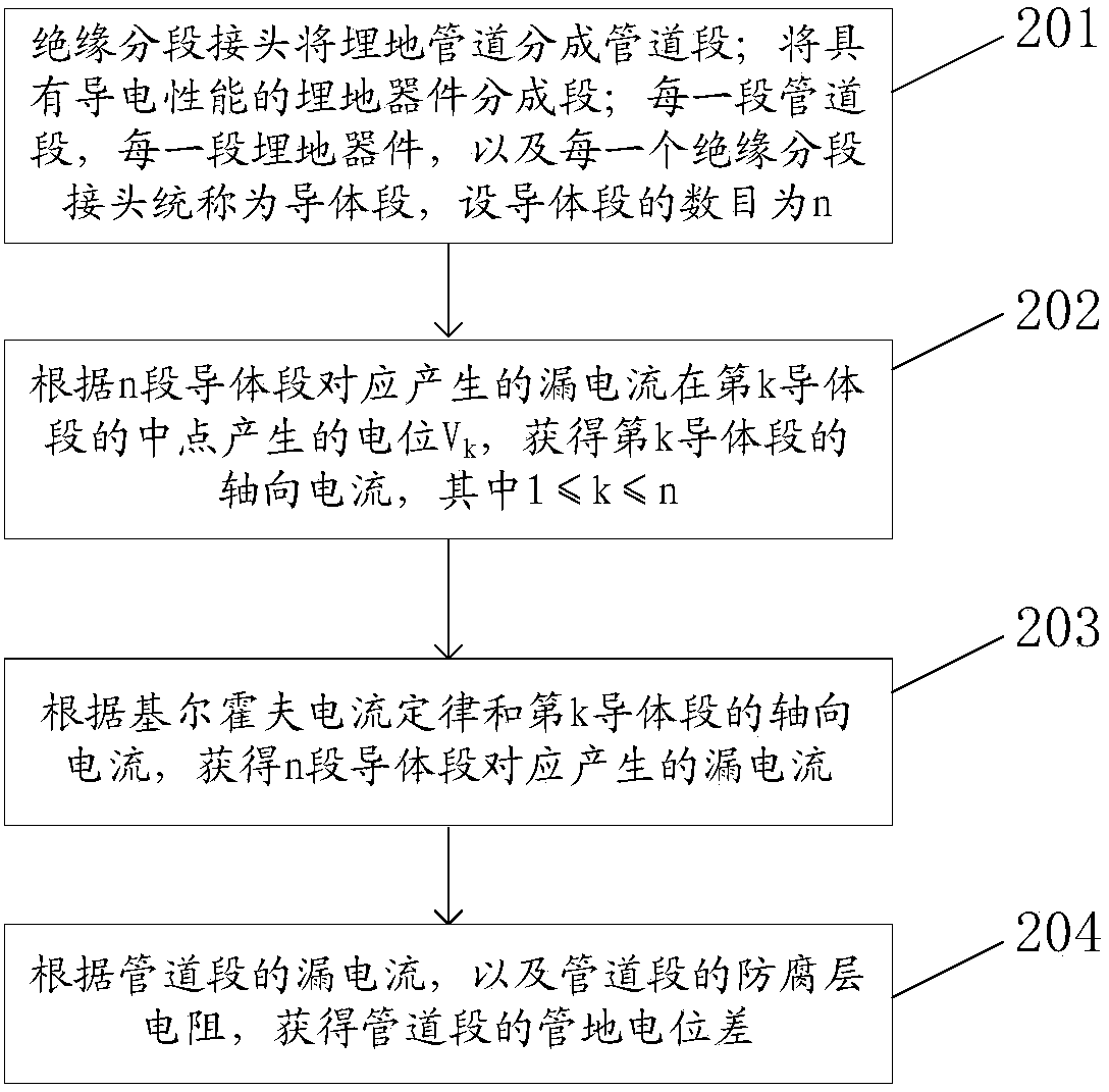
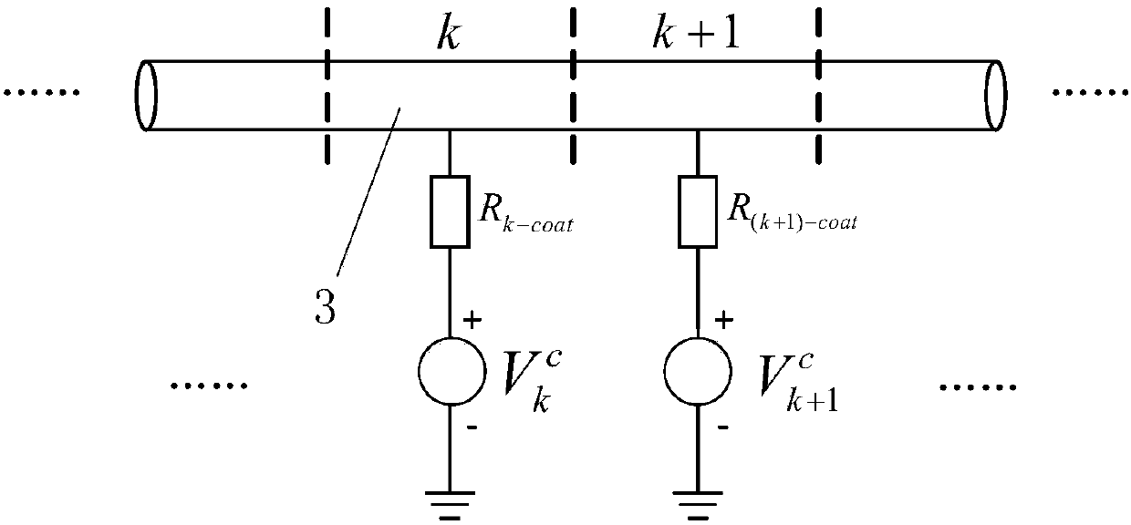
[0060] The buried pipeline 7 is a hollow buried cylindrical conductor covered with an insulating anti-corrosion layer 5. After the buried pipeline 7 is divided into several small sections by using insulating segment joints, the entire buried pipeline 7 is equivalent to being divided into several sections. A small section of hollow buried cylindrical conductor; the ground electrode 6 is a conductor or a combination of several conductors that are buried in the earth so as to be connected to the earth, and can also be regarded as a buried cylindrical conductor; The potential at one point is jointly produced by the leakage currents of all buried conductors; therefore, when calculating the pipe-to-ground potential of the buried pipeline 7, it is necessary to obtain the leakage current of each buried conductor at the corresponding position on the buried pipeline 7. current distribution.

[0061] see image 3 , the buried pipeline 7 is divided into several sections, and each buried ...

specific Embodiment

[0118] see Figure 9 The length of the buried pipeline 7 is 100km, the diameter of the buried pipeline 7 is 1219mm, the wall thickness of the buried pipeline 7 is 18.4mm, the material of the buried pipeline 7 is X80 steel pipe, and the resistivity of the three-layer PE anti-corrosion layer 5 is 10 5 Ω·m 2 . Soil characteristic parameters near grounding electrode 6: single layer soil, resistivity 1000Ω·m; grounding electrode 6 injected current 3000A, vertical distance between grounding electrode 6 and buried pipeline 7 is 5km. When no insulated section joint is added, the maximum pipe-to-ground potential of the buried pipeline 7 is 47.5V, and now the following optimization calculation is performed:

[0119] The maximum allowable pipe-to-ground potential of the buried pipeline 7 is set to 30V, and the number of insulation section joints expected to be added is set to two. The calculation result is obtained: the minimum pipe-to-ground potential difference is 28.2V, which is le...


PUM


Abstract

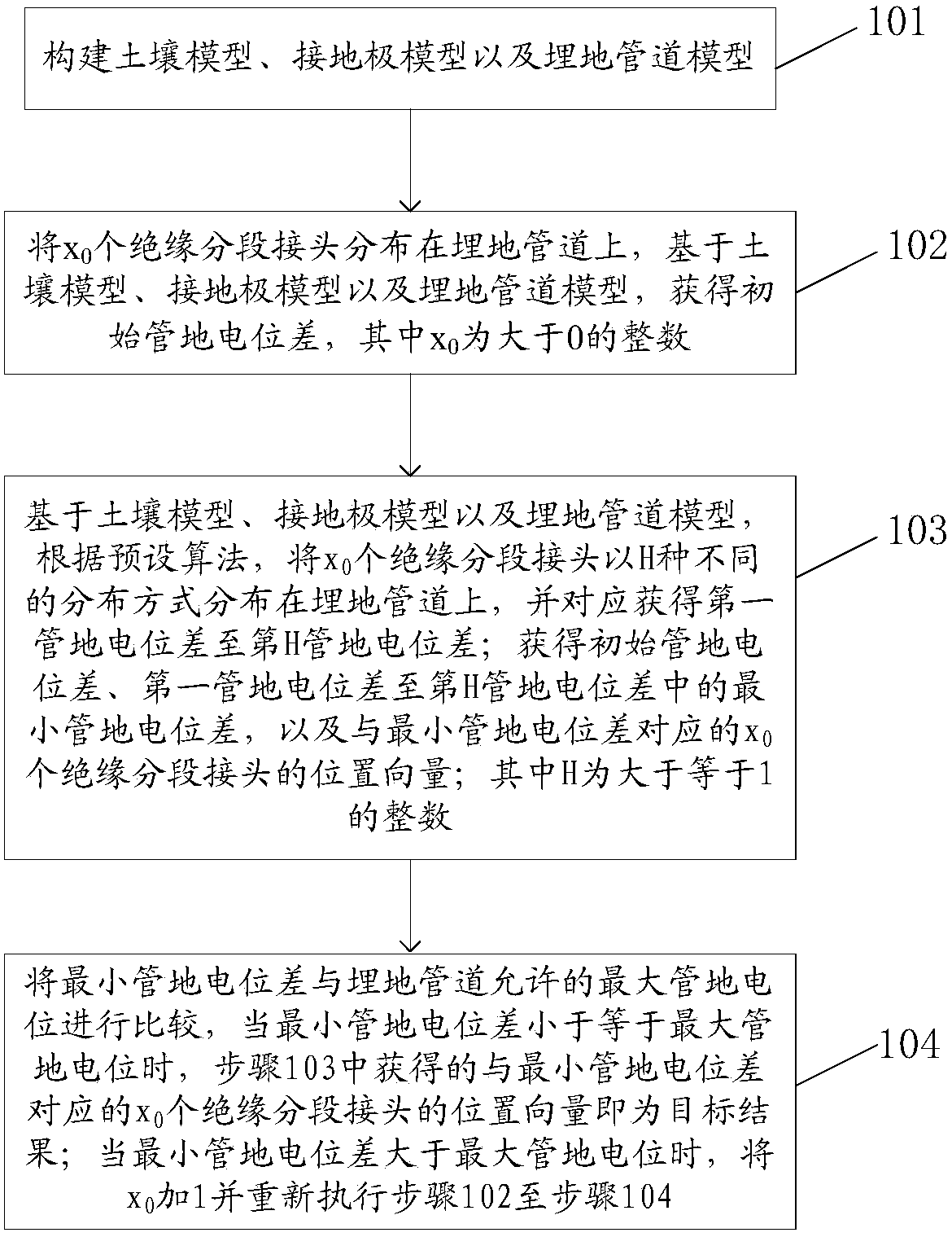
The invention discloses a method and an apparatus for arranging a buried pipeline in a sectional insulation manner, relates to the technical field of buried pipeline protection, and aims to solve the problems of low accuracy and lack of a standardized operation process for a method for performing sectional insulation design on the buried pipeline according to experience. The method for arranging the buried pipeline in the sectional insulation manner comprises the steps of obtaining an initial pipeline-soil potential difference and first to Hth pipeline-soil potential differences; obtaining a minimum pipeline-soil potential difference and a corresponding position vector; comparing the minimum pipeline-soil potential difference with a maximum pipeline-soil potential allowed by the buried pipeline, and when a condition is met, taking the obtained position vector corresponding to the minimum pipeline-soil potential difference as a target result; or otherwise, adding 1 to the number of insulated sectional connectors and obtaining the minimum pipeline-soil potential difference again until the condition is met. The method for arranging the buried pipeline in the sectional insulation manner, provided by the invention, is used for optimizing the arrangement of the buried pipeline in the sectional insulation manner.

Description

technical field [0001] The invention relates to the technical field of buried pipeline protection, in particular to a method and device for arranging segmental insulation of buried pipelines. Background technique [0002] With the continuous development of the power system, there are more and more long-distance and large-capacity power transmission projects. For such power transmission projects, in the prior art, power transmission is generally realized through a high-voltage DC grounded transmission system. This HVDC grounded power transmission system adopts a single-pole ground operation mode at the initial stage of operation, annual maintenance and troubleshooting, and when this mode of operation is adopted, the DC current injected into or extracted from the ground through the ground electrode can be as high as several Therefore, in this case, when the grounding electrode is relatively close to the buried pipeline used to transport oil and gas resources, the direct curren...

Claims


Application Information

Patent Timeline
Patent Type & Authority Patents(China)
IPC IPC(8): G06F17/50
CPCG16Z99/00
Inventor 廖永力张波孟晓波曾嵘邹林李锐海何金良曹方圆陈晓张巍吴新桥张贵峰张曦龚博朱烨
Owner ELECTRIC POWER RESEARCH INSTITUTE, CHINA SOUTHERN POWER GRID CO LTD
Learn More