
Projection image correction method and projection device

A technology for projecting images and projection devices, which is applied in the direction of using the image reproducer, image communication, and picture replicator of the projection device, can solve the problem that the projection device cannot automatically perform the correction of the projection image offset from the projection screen, and achieves the improvement of intelligence. Effect

Active Publication Date: 2016-09-28
TCL CORPORATION
View PDF4 Cites 35 Cited by
  • Summary
  • Abstract
  • Description
  • Claims
  • Application Information

AI Technical Summary

Problems solved by technology

[0004] In view of the deficiencies in the above-mentioned prior art, the purpose of the present invention is to provide users with a method and a projection device for correcting projected images, overcoming the fact that the projection device in the prior art cannot automatically correct the projected image offset from the projection screen, which requires Defects that are corrected manually

Method used


Image

  • Projection image correction method and projection device
  • Projection image correction method and projection device
  • Projection image correction method and projection device

Examples


Embodiment Construction

[0042] In order to make the object, technical solution and advantages of the present invention more clear and definite, the present invention will be further described in detail below with reference to the accompanying drawings and examples. It should be understood that the specific embodiments described here are only used to explain the present invention, not to limit the present invention.

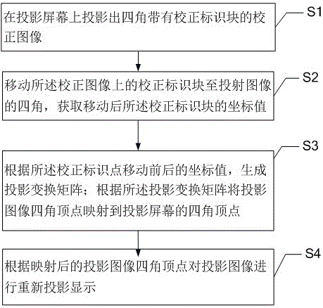
[0043] The present invention provides a projection image correction method, such as figure 2 As shown, the method includes the following steps:

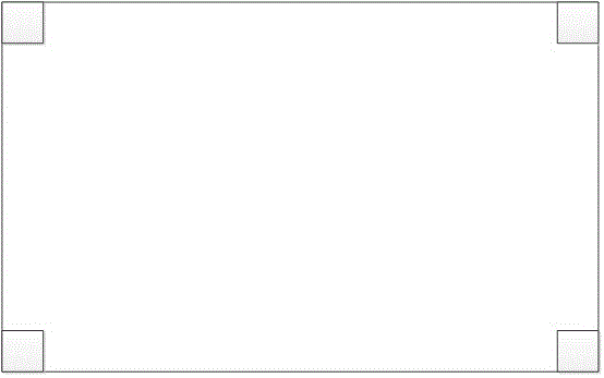
[0044] S1. Projecting a calibration image with calibration markers at four corners on a projection screen.

[0045] An image is projected on the projection screen, and the preset coordinate values ​​of the calibration mark points displayed when the image is projected on the projection screen are acquired.

[0046] In order to obtain the calibration mark points in the projection image, it is necessary to set up the projection device in advanc...


PUM


Abstract

The invention provides a projection image correction method and a projection device. The method comprises the steps of projecting a correction image of which four angles are equipped with correction identification points in a projection screen; moving the correction identification points in the correction image to the four angles of the projection screen; obtaining the coordinate values of the correction identification points in the correction image after movement; and projecting the coordinate values of the four vertex angles of the original projection image to the coordinates of the correction identification points according to an image geometric correction algorithm and carrying out image projection display according to the coordinate values after projection, thereby correcting the projection image automatically by the projection device. According to the method, the system and the projection device, the image geometric correction is realized by the low cost method without a camera or an accelerometer, the projection image and the projection screen can be matched precisely, the intelligence of the projection device is improved, and moreover, convenience is provided for a user.

Description

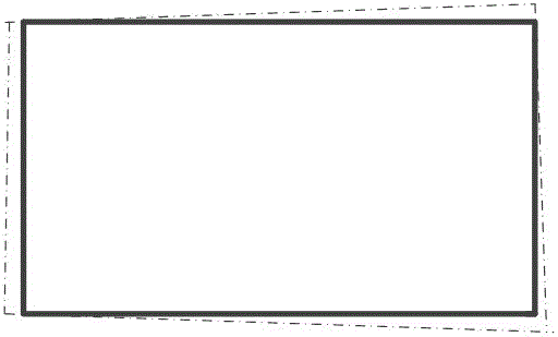
technical field [0001] The invention relates to a projection image correction method and a projection device. Background technique [0002] At present, projection TVs are becoming more and more popular in the market, especially ultra-short-throw projection TVs, but when installing projection TVs, the TV screen needs to be projected on the screen just right, and installation is very difficult, especially when the desktop where the projector is placed is not. If the wall where the projection screen is installed is flat or uneven, it is generally difficult for the picture to match the projection screen well, and it is easy to produce such as figure 1 The effect matches, and because the projected image is trapezoidal, it affects the viewing effect and causes inconvenience to the user's viewing. [0003] Therefore, prior art awaits further improvement. Contents of the invention [0004] In view of the deficiencies in the above-mentioned prior art, the purpose of the present i...

Claims


Application Information

Patent Timeline
IPC IPC(8): H04N9/31
CPCH04N9/3185
Inventor 施建华邓益群
Owner TCL CORPORATION
Learn More