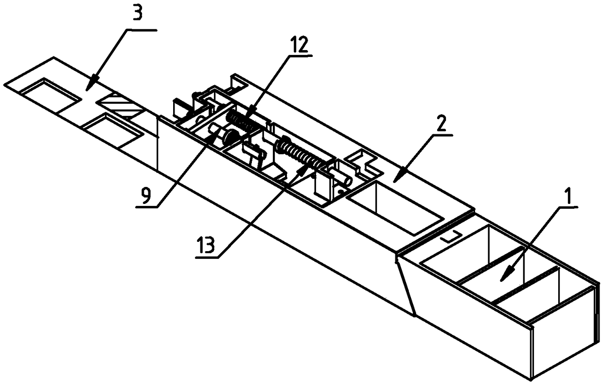
A drawer and a cabinet body containing the drawer
A drawer and cabinet technology, applied in drawers, cabinets, chests of drawers, etc., can solve the problems of toxicity, addiction, etc., and achieve the effects of improving safety, low cost, and saving installation space
- Summary
- Abstract
- Description
- Claims
- Application Information
AI Technical Summary
Problems solved by technology
Method used
Image
Examples
Embodiment 1
[0030] Such as Figure 1-2 As shown, a drawer includes a drawer body 1, a connecting plate 4, a fixing assembly 3 and a locking assembly 2. Medicine compartments are arranged inside the drawer body 1 for storing medicines, and the fixing assembly 3 is located under the drawer body 1. The drawer body 1 and the locking assembly 2 are connected through the connecting plate 4 to ensure that the drawer body 1 and the locking assembly 2 move synchronously, and through the synergistic effect of the fixing assembly 3 and the locking assembly 2, the locking and unlocking operations of the drawer body 1 are realized. Helps improve the safety of drug regulation.
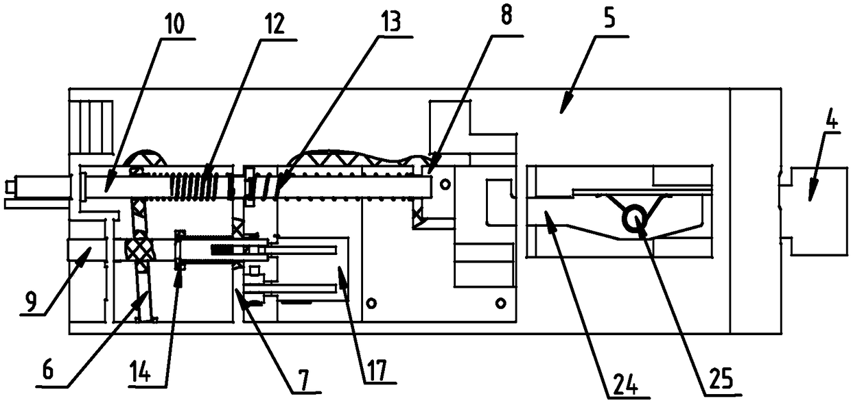
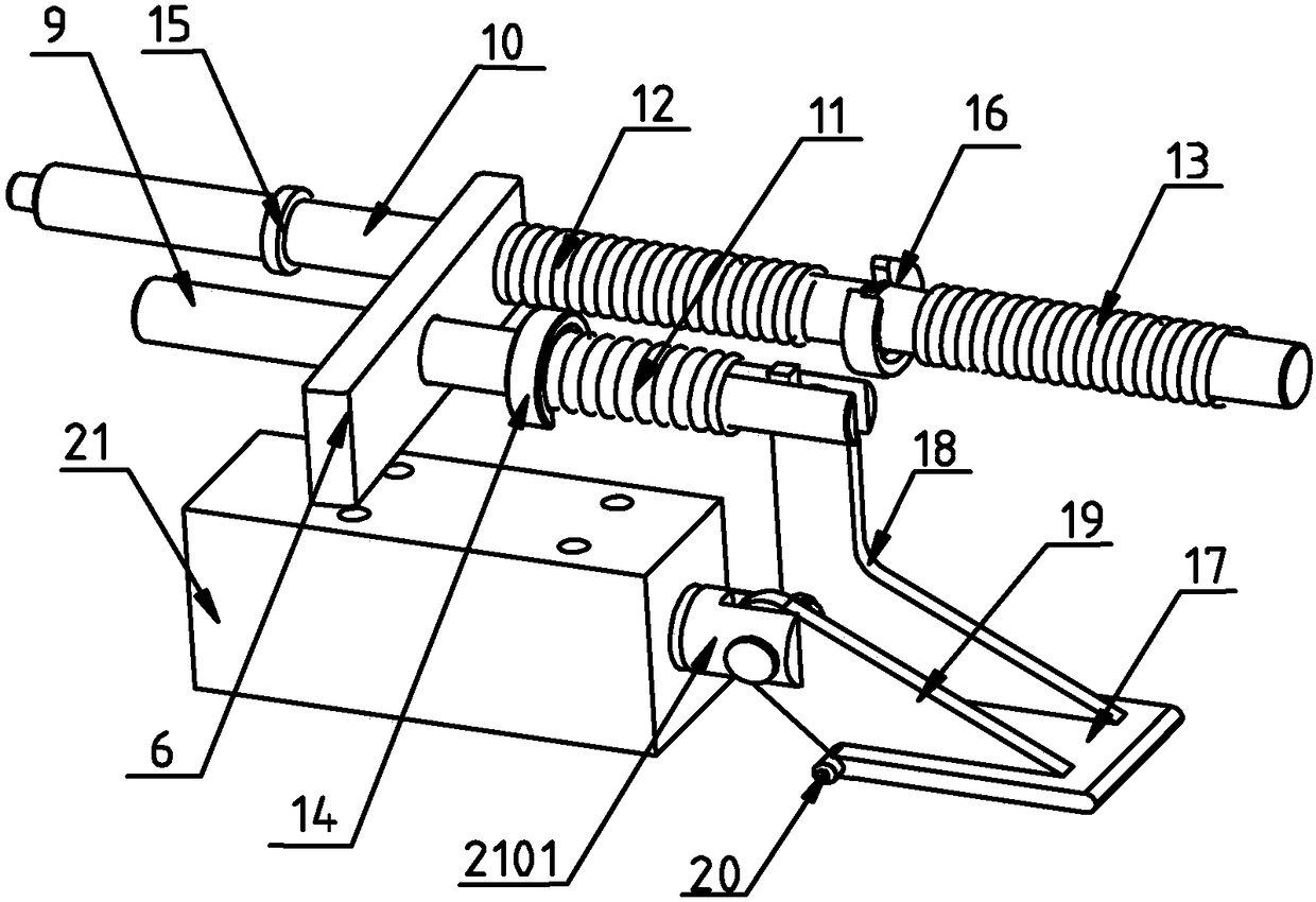
[0031] Such as Figure 1-5 As shown, the locking assembly 2 includes a lock body 5, a stop mechanism and a rebound mechanism. The stop mechanism and the rebound mechanism are both located inside the lock body 5 and pass through the lock body 5 respectively. Matching, used for locking or unlocking the drawer body 1.
[0032] ...
Embodiment 2
[0038] Such as Figure 1-5 As shown, the connecting plate 4 is provided with a limiting plate 24 and a fastener 25, the limiting plate 24 and the connecting plate 4 are movably connected by the fastener 25, and the limiting plate 24 can rotate around the fastener 25, The fastener 25 is provided with a reset member 23 for resetting the rotated limiting plate 24. The end of the limiting plate 24 is provided with a hook pin 2401. During the process of pulling the drawer body 1 , the hook pin 2401 moves along the edge of the clamping plate 26, and the end of the clamping plate 26 is provided with a limit block 2602. When the hook pin 2401 is in contact with the limit block 2602, the drawer body 1 is at the maximum withdrawal limit. At this time, the rotation limit plate 24, the hook pin 2401 is separated from the limit block 2602, the drawer body 1 and the locking assembly 2 can be separated, and the drawer body 1 can be completely disassembled.
[0039] The fixed plate 7 is prov...
Embodiment 3
[0041] Such as Figure 1-6 As shown, a cabinet body 22 includes the above-mentioned drawer, the fixing assembly 3 is located inside the cabinet body 22 and is fixedly connected with the cabinet body 22, and an auxiliary part 28 is provided through the inside of the cabinet body corresponding to the locking pin 9 .
[0042] The initial state of the cabinet body 22 is that the drawer body 1 is in a locked state. At this time, after the end of the guide rod 10 is in contact with the inner wall of the cabinet body 22, the end of the locking pin 9 and the auxiliary part 28, the guide rod 10 will , locking pin 9 all produce axial displacement relative to lock body 5, in the present embodiment, guide rod 10, locking pin 9 move outwards relative to lock body 5 (that is, along Image 6 middle and lower right), when the axial displacement of the locking pin 9 relative to the lock body 5 reaches the limit, the bottom of the stop block 17 contacts and engages with the drawer groove 2601,...
PUM
 Abstract
Description
Claims
Application Information
 - R&D
- Intellectual Property
- Life Sciences
- Materials
- Tech Scout
- Unparalleled Data Quality
- Higher Quality Content
- 60% Fewer Hallucinations
Browse by: Latest US Patents, China's latest patents, Technical Efficacy Thesaurus, Application Domain, Technology Topic, Popular Technical Reports.
© 2025 PatSnap. All rights reserved.Legal|Privacy policy|Modern Slavery Act Transparency Statement|Sitemap|About US| Contact US: help@patsnap.com


