Ultraviolet germicidal lamp
A technology of ultraviolet and germicidal lamps, which is applied in the direction of lighting devices, lighting and heating equipment, and parts of lighting devices, to achieve the effect of simple structure, ingenious design, and changing the irradiation area
- Summary
- Abstract
- Description
- Claims
- Application Information
AI Technical Summary
Problems solved by technology
Method used
Image

Examples
Embodiment 1
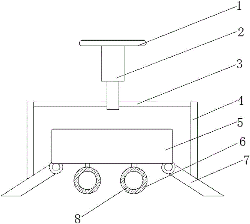
[0017] Embodiment 1: When the electronic telescopic rod 2 becomes shorter, the cross bar 3 moves upward with the column 4, and the column 4 moves upward with the reflector 7, thereby increasing the angle between the reflector 7 and the fixed seat 1, thereby increasing the The irradiated area is increased, and the distance between the ultraviolet lamp tube 8 and the irradiated object is increased at the same time.
Embodiment 2
[0018] Embodiment 2: When the electronic telescopic rod 2 becomes longer, the cross bar 3 moves downward with the column 4, and the column 4 moves downward with the reflector 7, thereby reducing the angle between the reflector 7 and the fixed seat 1, and then The irradiated area is reduced, and at the same time, the distance between the ultraviolet lamp tube 8 and the irradiated object is reduced.
PUM
 Abstract
Description
Claims
Application Information
 - R&D
- Intellectual Property
- Life Sciences
- Materials
- Tech Scout
- Unparalleled Data Quality
- Higher Quality Content
- 60% Fewer Hallucinations
Browse by: Latest US Patents, China's latest patents, Technical Efficacy Thesaurus, Application Domain, Technology Topic, Popular Technical Reports.
© 2025 PatSnap. All rights reserved.Legal|Privacy policy|Modern Slavery Act Transparency Statement|Sitemap|About US| Contact US: help@patsnap.com