Pipe bending machine and pipe bending method

A pipe bending machine and pipe material technology, applied in the field of pipe bending, can solve the problems affecting the quality of metal bending pipe products, easy to break and damage, etc., and achieve the effect of reducing the fracture damage and high quality of the pipe end

Active Publication Date: 2018-09-18
OMS MASCH CO LTD
View PDF7 Cites 2 Cited by
  • Summary
  • Abstract
  • Description
  • Claims
  • Application Information

AI Technical Summary

Problems solved by technology

Although the bending method of the metal pipe in the prior art can realize the conversion of the metal pipe from a straight pipe to a bent pipe, the clamping position corresponding to the clamp on the metal pipe is clamped by the clamp for a long time and relatively large during the bending process. Holding force, the clamping part of the metal pipe is extremely prone to breakage and damage, which will affect the product quality of the metal bending pipe

Method used


Image

  • Pipe bending machine and pipe bending method
  • Pipe bending machine and pipe bending method
  • Pipe bending machine and pipe bending method

Examples


Embodiment Construction

[0036] Embodiments of the present invention are described in detail below:

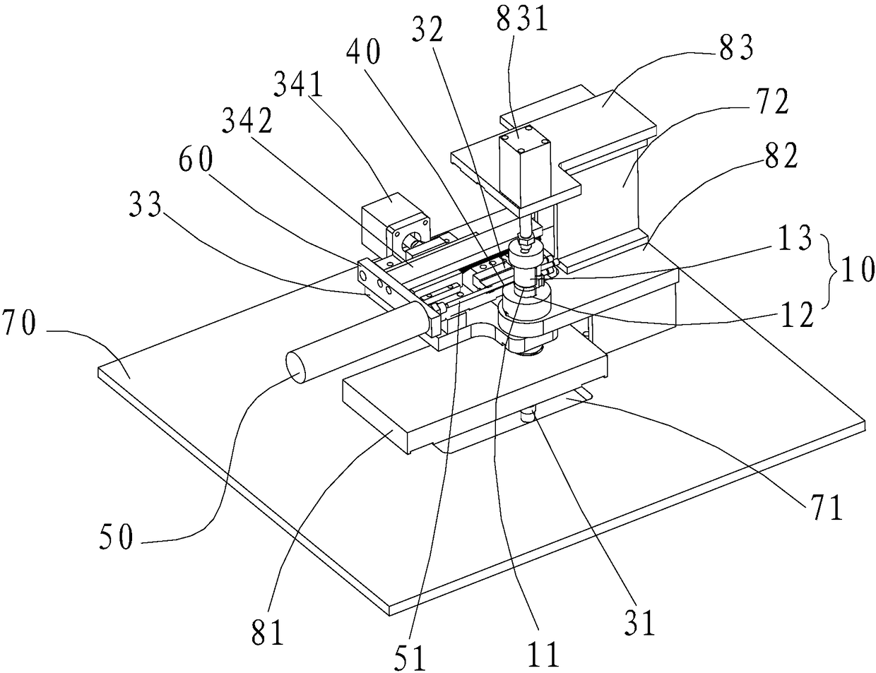
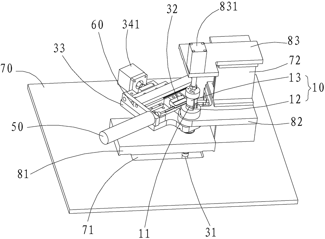
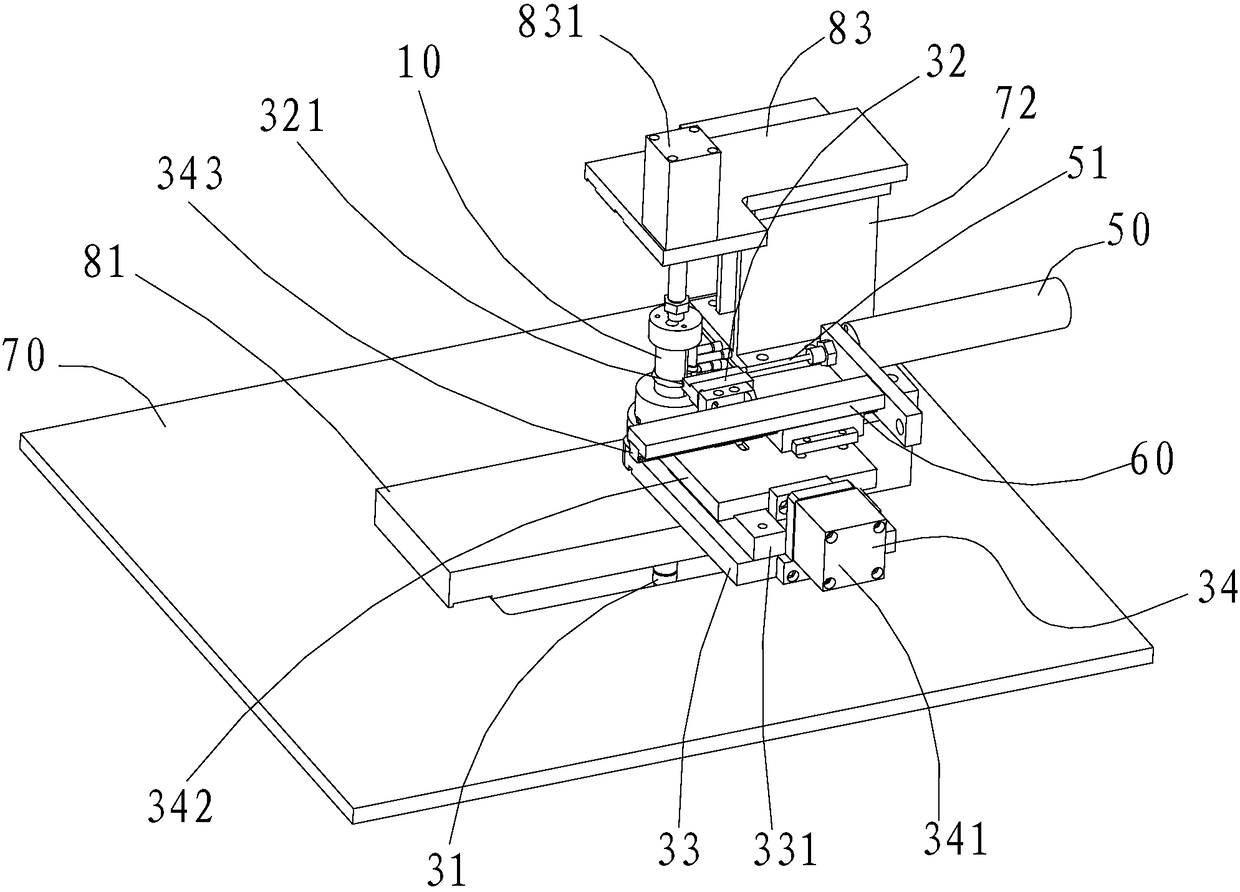
[0037] Such as Figure 1-5 As shown, the pipe bender of the present invention includes a guide column 10, a fixing member 20, a rotating mechanism 30 (in Figure 7-10 There are marks in it) and the first driving part 831. A first recess 11 is formed on the side wall of the guide column 10 . The first recess 11 is arranged around the guide cylinder 10 around the axis of the guide cylinder 10 , and the first recess 11 is adapted to the outer wall of the pipe 40 . Wherein, the guide cylinder 10 includes a first cylinder 12 and a second cylinder 13 arranged coaxially (see Figure 6 ). And the first cylinder 12 and the second cylinder 13 can move towards or back, the outer wall of the end of the first cylinder 12 has a first concave surface 121, and the outer side of the end of the second cylinder 13 is The wall has a second concave surface 131 . The first concave surface 121 is spliced ​​with the se...


PUM


Abstract

The invention discloses a pipe bending machine and a pipe bending method. The pipe bending machine comprises a guide column body, a fixing piece and a rotating mechanism, wherein a first recess is formed in the side wall of the guide column body; the first recess surrounds the guide column body by taking the axis of the guide column body as a center and is matched with the outer side wall of a pipe; the fixing piece is used for fixing the pipe on the guide column body; the rotating mechanism comprises a driving piece and a propping piece; the propping piece is provided with a second recess which is opposite to the first recess and is matched with the outer side wall of the pipe; and the driving piece is used for driving the propping piece to move along the first recess of the guide column body. According to the pipe bending machine, a pipe clamping end, namely the fixing piece, stays in a fixed state, and a bending forming mechanism, namely the rotating mechanism, dynamically changes to gradually bend the pipe, so that the phenomenon that one end part of the pipe is broken and damaged because the pipe clamping end exerts a large acting force on the end part for a long time can be overcome; and compared with a bending machine in the prior art, the pipe bending machine can produce a higher-quality bent pipe.

Description

technical field [0001] The invention relates to the technical field of pipe bending, in particular to a pipe bending machine and a pipe bending method. Background technique [0002] The traditional bending method of bending metal pipes such as copper pipes, aluminum pipes, and iron pipes from straight pipes into curved pipes is: the bending machine is equipped with an arc-shaped channel suitable for the metal pipe, and the metal pipe is clamped by the clamp. The metal tube is gradually moved along the arc channel, and the metal tube is converted from a straight tube to a curved tube during the process of moving along the arc channel. Although the bending method of the metal pipe in the prior art can realize the conversion of the metal pipe from a straight pipe to a bent pipe, the clamping position corresponding to the clamp on the metal pipe is clamped by the clamp for a long time and relatively large during the bending process. Holding force, the clamping part of the metal...

Claims


Application Information

Patent Timeline
Patent Type & Authority Patents(China)
IPC IPC(8): B21D9/07B21D43/00
CPCB21D9/073B21D43/003
Inventor 龙晓斌王海军何汉强谢湘峰覃丽
Owner OMS MASCH CO LTD
Why Eureka
Try Eureka