Numerical control pipe bend forming device

A bending forming and pipe technology, applied in the field of pipe bending, can solve the problems of low production efficiency, cumbersome and complicated operation, deformation, etc., and achieve the effect of improving production efficiency

Inactive Publication Date: 2017-07-14
FOSHAN TIANJIAN MECHANICAL CO LTD
View PDF5 Cites 3 Cited by
  • Summary
  • Abstract
  • Description
  • Claims
  • Application Information

AI Technical Summary

Problems solved by technology

[0002] Existing pipe benders generally can only bend the pipe in one direction. However, in the process of use, the copper pipe needs to be bent in two directions, forward and reverse. Usually, the steering mechanism for turning the copper pipe is used to match the one-way bending of the pipe bender. Bending to achieve forward and reverse bending, or to achieve bending in different directions by changing the bending di

Method used


Image

  • Numerical control pipe bend forming device
  • Numerical control pipe bend forming device
  • Numerical control pipe bend forming device

Examples


Embodiment Construction

[0016] The present invention will be further described below in conjunction with specific examples.

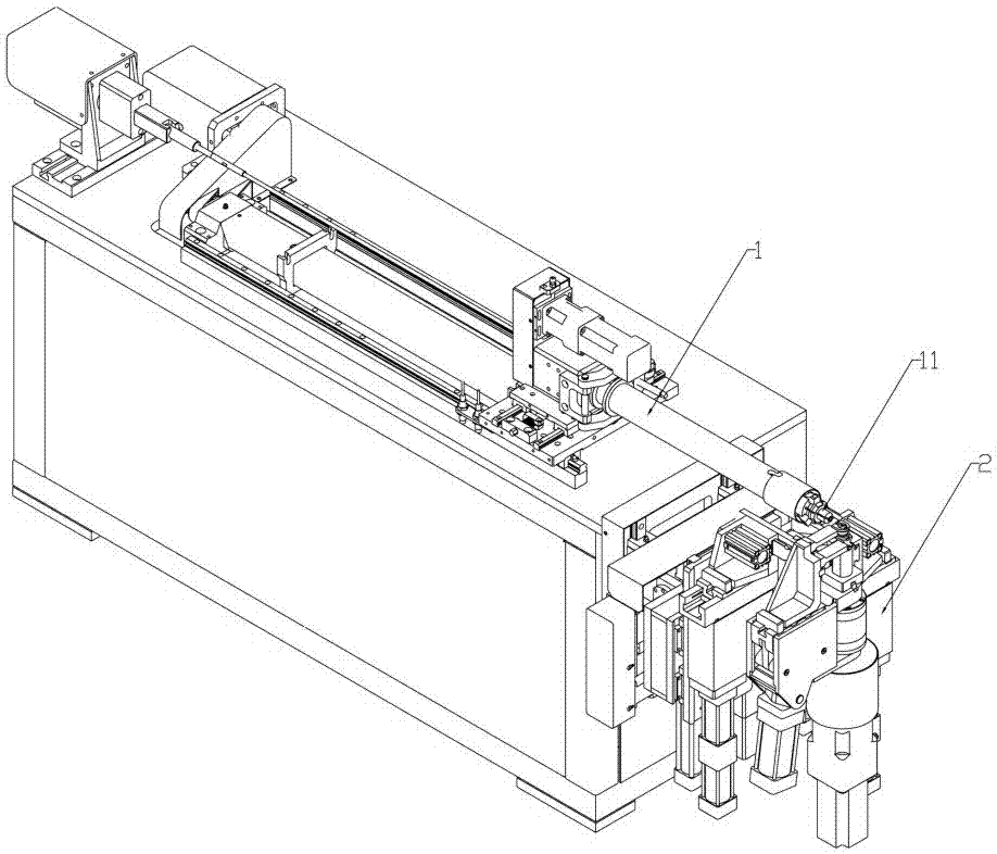
[0017] See attached figure 1 As shown, in this embodiment, a numerical control pipe bending and forming device includes a feeding rotating mechanism 1 and a pipe bending mechanism 2 installed on the frame and used for pipe transportation, wherein the output of the feeding rotating mechanism 1 The nozzle is provided with a pipe clamp 11 for clamping the pipe; the pipe bending mechanism 2 is located at the pipe outlet of the feeding rotating mechanism 1; the feeding rotating mechanism 1 realizes the transportation of the pipe and the support and clamping of the pipe.

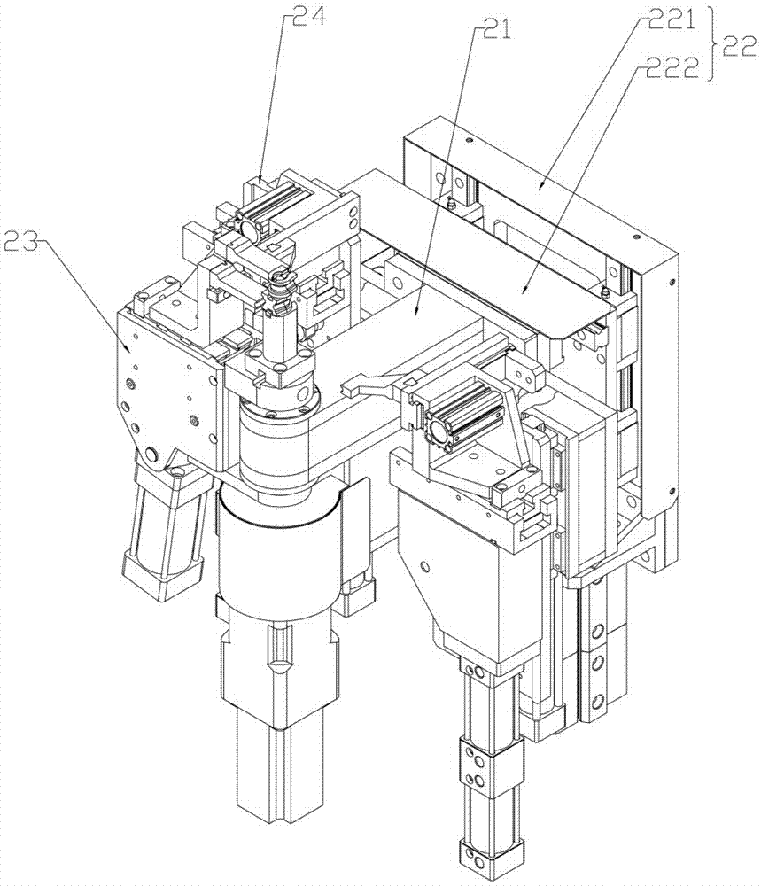
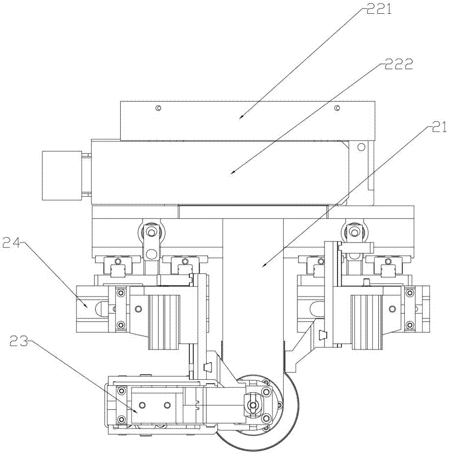
[0018] See attached figure 2 to attach Figure 5 As shown, in this embodiment, the pipe bending mechanism 2 includes a connecting seat 21, an adjustment assembly 22 for driving the connecting seat 21 to move vertically and horizontally, a bending clamping assembly 23, and two groups of The cam assembly 24 arra...


PUM


Abstract

The invention provides a numerical control pipe bend forming device. The device comprises a feed rotating mechanism mounted on a frame for conveying pipes, and a pipe bending mechanism; the pipe bending mechanism is positioned in a pipe outlet of the feed rotating mechanism; the pipe bending mechanism comprises a connecting base, an adjusting module for driving the connecting base to move in the vertical direction and the horizontal direction, a bend clamping module, and two sets of profiling modules respectively arranged on two sides of the connecting base; the bend clamping module comprises a rotating arm rotationally connected with the connecting base, a rotating motor for driving the rotating arm to rotate along a vertical rotating shaft, a mold bending base and a mold clamping base; and the profiling modules comprise profiling bases, profiling cushion plates and profiling mounting plates. The numerical control pipe bend forming device realizes left-right bending formation, is not liable to generate deformation in the pipe bending process, is better in bending quality, and is high in production efficiency.

Description

technical field [0001] The invention relates to the technical field of pipe bending, in particular to a numerically controlled pipe bending device. Background technique [0002] Existing pipe benders generally can only bend the pipe in one direction. However, in the process of use, it is necessary to bend the copper pipe in both forward and reverse directions. Usually, the steering mechanism for turning the copper pipe is used to cooperate with the one-way bending of the pipe bender. Bending to achieve forward and reverse bending, or to achieve bending in different directions by changing the bending die, but the operation of the steering mechanism is cumbersome and complicated; the production efficiency is not high by replacing the bending die; secondly, multiple bending The direction and angle of the pipe bender are not the same, and it is easy to cause the bending not in place, and the deformation of the position that does not need to be bent, etc., so that the pipe bender...

Claims


Application Information

Patent Timeline
IPC IPC(8): B21D7/06
CPCB21D7/063
Inventor 黄伟明韦仲华
Owner FOSHAN TIANJIAN MECHANICAL CO LTD
Why Eureka
Try Eureka