A kind of manipulator and method with rotating pallet

A technology of rotating pallets and manipulators, applied in the field of manipulators, can solve the problem of not being able to hold multiple pieces to be clamped, and achieve the effect of compact manipulators and small width and space.

Active Publication Date: 2019-02-15
JINAN ZHONGRUN AUTOMATIC CONTROL EQUIP
View PDF11 Cites 0 Cited by
  • Summary
  • Abstract
  • Description
  • Claims
  • Application Information

AI Technical Summary

Problems solved by technology

This kind of manipulator can only clamp a single piece to be clamped, and cannot satisfy multiple clamped pieces to be clamped together

Method used


Image

  • A kind of manipulator and method with rotating pallet

Examples


Embodiment Construction

[0024] The present invention is described in detail below in conjunction with accompanying drawing:

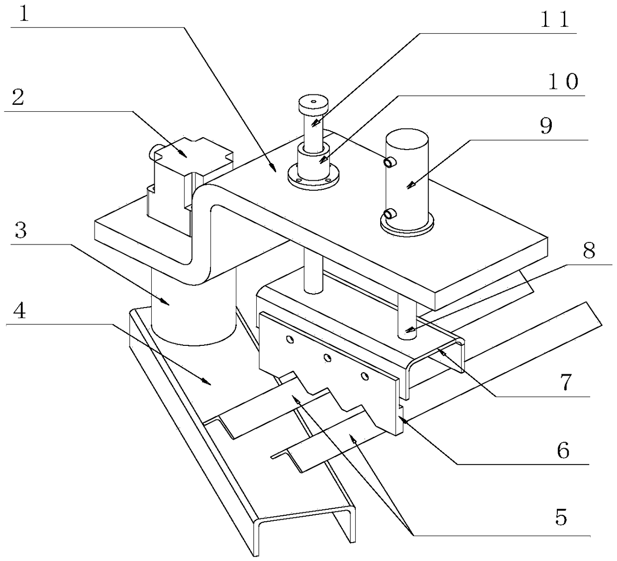
[0025] The present invention comprises a palm, a rotating supporting plate and a claw pressing plate. The rotating supporting plate and the claw pressing plate are located on the same side of the palm, and in the height direction, the position of the rotating supporting plate is higher than that of the claw pressing plate. Low; the driving device I that drives the rotation of the rotating pallet and the driving device II that drives the claw pressing plate to move up and down relative to the rotating pallet are installed on the palm; the claw pressing plate and the rotation are adjusted by the driving device I and the driving device II The relative position of the supporting plate is used to realize the upper and lower clamping of the parts to be clamped. The rotating pallet is fixed in the height direction, and it only performs rotational movement; the claw pressing plate onl...


PUM


Abstract

The invention discloses a mechanical hand with a rotary supporting plate and a method. The mechanical hand comprises a palm, the rotary supporting plate and a paw pressing plate; the rotary supporting plate and the paw pressing plate are located on the same side of the palm; in the height direction, the position of the rotary supporting plate is lower than that of the paw pressing plate; a first driving device for driving the rotary supporting plate to rotate and a second driving device for driving the paw pressing plate to move up and down relative to the rotary supporting plate are installed on the palm; the relative positions of the paw pressing plate and the rotary supporting plate are adjusted through the first driving device and the second driving device so that to-be-clamped pieces can be clamped in an up-down mode.

Description

technical field [0001] The invention relates to a manipulator, which is suitable for a plurality of parts to be clamped with large weight and volume, in particular to a manipulator with a rotating pallet and a method thereof. Background technique [0002] The manipulator is an important part of the robot. The general manipulator is driven by the cylinder to clamp and release the mechanical parts to be clamped from the left and right sides. to realise. [0003] At present, the clamping parts of common manipulators on the market are generally small, and cannot clamp the parts to be clamped that are heavy or bulky. When clamping a heavy or bulky piece to be clamped, generally fix the bottom plate of the manipulator, add a push-out mechanism of the manipulator, and push the placed piece to be clamped out of the manipulator. This manipulator has a complex mechanical structure and a large volume. There are also manipulators that add a hook mechanism. The hook clip is installed ...

Claims


Application Information

Patent Timeline
Patent Type & Authority Patents(China)
IPC IPC(8): B25J15/08B25J9/08
CPCB25J9/08B25J15/08
Inventor 王炎
Owner JINAN ZHONGRUN AUTOMATIC CONTROL EQUIP
Why Eureka
Try Eureka