Rehabilitation standing bed

A bed board and bed head technology, applied in the field of rehabilitation standing beds, can solve the problems of insufficiently optimized structure, weak use safety, poor movement stability of the bed board, etc., and achieve the effect of simple structure design, guarantee of use safety, and ingenious structure design.

Active Publication Date: 2018-11-13
义乌市航英科技有限公司
View PDF13 Cites 0 Cited by
  • Summary
  • Abstract
  • Description
  • Claims
  • Application Information

AI Technical Summary

Problems solved by technology

It has the following disadvantages: the inner bed frame rotates around its middle part, and the space below the inner bed frame needs to be high enough, and the space within a certain height above the side where the head end of the inner bed frame is located is wide enough, and the applicability is poor; drive, and the stability of bed board movement is poor, and its use safety is relatively weak; it is necessary to set up a special support bracket, and the structure is not optimized enough
It has the following disadvantages: when the frame of the bed surface is rotated, a larger width space needs to be left within a certain height above the side where the head end is located, and the applicability is poor; the distance between the driving action point and the head end of the bed surface is relatively large. Large, it needs to consume more energy. If the driving point is set close to the head of the bed, the arc formed by its rotation is relatively large, which is not conducive to direct driving, and the drive is more inconvenient; the stability of the movement of the bed skeleton is relatively Poor, its use safety is relatively weak; special support brackets need to be set up, and the structure is not optimized enough

Method used


Image

  • Rehabilitation standing bed
  • Rehabilitation standing bed
  • Rehabilitation standing bed

Examples


Embodiment

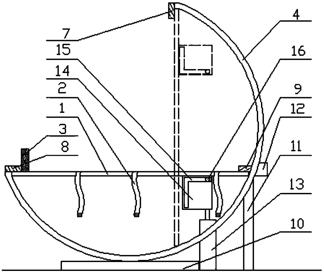
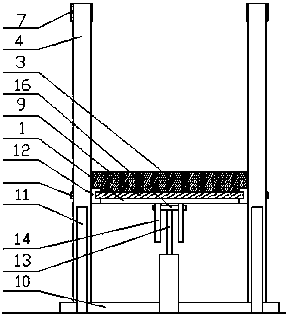
[0026] Such as figure 1 and figure 2 A rehabilitation standing bed shown includes a bed board 1 and a bed frame, the bed board 1 is provided with a strap 2 for binding the user, and the bed end of the bed board 1 is provided with a footboard 3; The frame includes two arc-shaped support rails 4 that are parallel to each other and are supported on the two lengths of the bed board 1 along the sides. The bottoms of the two support rails 4 are fixedly installed on the ground. The other end of the track 4 passes through the bottom of the bed board 1 and goes out from the head end of the bed board 1 and extends upward to directly above the bed board 1. The head end of the bed board 1 is located on the support rail 4, and the arc of the support rail 4 corresponds to the central angle The value of the range is [180,270) (the central angle corresponding to the arc of the support track 4 shown in the figure is 225 °); the inner surface of the support track 4 is provided with a slide ra...


PUM


Abstract

The invention discloses a rehabilitation standing bed, and belongs to the field of medical rehabilitation equipment. The rehabilitation standing bed comprises a bed board and a bed frame, the bed frame comprises two arc supporting frames supported on the two sides of the bed board, the ends of the supporting frames are located at the tail end of the bed board, and the other ends of the supportingframes pass the lower side of the bed board, penetrate out of the bed head end of the bed board, and extend upward; sliding rails extending along the radian of the supporting frames are arranged on the inner side surfaces of the supporting fames, sliding blocks matched with the sliding rails are arranged at the two ends of the bed board, an upper fixed baffle plate and a lower fixed baffle plate are correspondingly arranged at the upper and lower ends of the supporting frames, and moving baffle plates movably connected with the supporting frames are arranged on the positions, corresponding tothe bed head end of the bed board, on the supporting frames; a lifting driving device is connected to the side where the bed head end of the bed board is located. According to the bed, the arc slidingrails used for the two ends of the bed board to move are arranged to conveniently drive the bed board to move, the moving stability of the bed board can be ensured, and the using safety of the bed isfurther ensured; the sliding rails supply the supporting effect to the bed board, the structure design is simple and ingenious, the required operating space is less, and the adaptability is higher.

Description

technical field [0001] The invention relates to the field of medical rehabilitation equipment, in particular to a rehabilitation standing bed. Background technique [0002] Paralyzed patients, vegetative patients and other patients are bedridden for a long time and have limited mobility. They need specially designed products for standing exercises to prevent and improve complications such as osteoporosis, decubitus ulcers, and cardiac function decline. The products currently on the market that are used for this group of people to exercise are all standing stands that are used alone and have a relatively single function. During operation, if you want to transfer the patient from the nursing bed to the standing stand, you need a lot of people to help together or to complete it with the help of other transfer equipment. Not only increased the patient's expenses, but also very troublesome in actual operation. [0003] At present, there are many sick beds with the function of tu...

Claims


Application Information

Patent Timeline
Patent Type & Authority Applications(China)
IPC IPC(8): A61G7/005A61G7/05
CPCA61G7/005A61G7/05A61G2203/10A61H2201/0142A61H2203/0406
Inventor 刘阳李晓华付乃胜邢章民张振国刘云田
Owner 义乌市航英科技有限公司
Why Eureka
Try Eureka