
Umbrella cloth cutting and waste recycling device

A technology of waste recycling and umbrella cloth, which is applied in the direction of metal processing, etc., can solve problems such as troublesome, unreasonable structural design of the cutting device, and inability to effectively contact the umbrella cloth.

Inactive Publication Date: 2016-10-12
程志刚
View PDF4 Cites 2 Cited by
  • Summary
  • Abstract
  • Description
  • Claims
  • Application Information

AI Technical Summary

Problems solved by technology

Umbrella cloth needs to be dried after being processed and shaped. After drying, it needs to be rolled up. Before winding, it needs to be cut to a fixed width. The original cutting device structure design is unreasonable, and the position of the cutting blade is fixed, resulting in a long time cutting knife. The disk cannot effectively contact the umbrella cloth, and the cut umbrella cloth waste strip and the umbrella cloth with a fixed width are intermittent and cannot be separated directly, and secondary cutting is required manually, which brings unnecessary troubles to production and processing
In addition, it is cumbersome if the waste is not recycled before. It is necessary to design the waste winding roller shaft. After winding, it needs to be disassembled from the waste winding roller shaft again, which is more troublesome.

Method used


Image

  • Umbrella cloth cutting and waste recycling device

Examples


Embodiment Construction

[0007] The umbrella cloth cutting and waste recycling device of the present invention will be further described below in conjunction with specific embodiments.

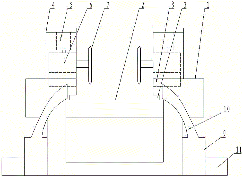
[0008] Depend on figure 1 It can be seen that the umbrella cloth cutting and waste recycling device of the present invention includes a bracket 1 installed on the discharge port of the drying equipment, a rotating shaft 2 is installed on the bracket 1, and the inner side wall of the bracket 1 above the rotating shaft 2 is symmetrically arranged. There is an umbrella cloth discharge limit groove 3, a door-shaped support frame 4 is installed symmetrically on the left and right sides of the upper end surface of the support 1, and a downward cylinder 5 is installed on the crossbeam of the support frame 4, and the end of the piston rod of the cylinder 5 is fixed. There is a motor 6, the end of the output shaft of the motor 6 is fixedly equipped with a cutter head 7, the cutter head 7 is perpendicular to the movement track ...


PUM


Abstract

The invention discloses an umbrella cloth cutting and waste recycling device which comprises a bracket mounted at a material outlet of drying equipment; a rotating shaft is mounted on the bracket; umbrella cloth discharging limiting slots are symmetrically formed in the positions, above the rotating shaft, on the inner side wall of the bracket; door-shaped supporting racks are symmetrically mounted on the left and right sides of the upper end surface of the bracket; downward cylinders are mounted on cross beams of the supporting racks; motors are fixedly mounted at the end parts of piston rods of the cylinders; cutterheads are fixedly mounted at the end parts of output shafts of the motors and are perpendicular to the moving trace of a piece of umbrella cloth; travel slots matched with the outer walls of the motors are formed in positions, below the motors, on the upper end surfaces of the bracket; recycling drums are further mounted on the ground outside the bracket; suction fans are mounted on the outer sides of the recycling drums; recycling pipes are arranged at the upper ends of the suction fans; and pipe orifices of the recycling pipes face the discharging limiting slots. The umbrella cloth cutting and waste recycling device is novel in structural design; a gap between each cutterhead and the umbrella cloth is adjustable, so that cutting can be completed at one time; and meanwhile, wastes are convenient and quick to recycle, so that the processing efficiency and the quality are improved.

Description

technical field [0001] The invention relates to a cutting and recycling device, in particular to an umbrella cloth cutting and waste recycling device. Background technique [0002] An umbrella is a tool that provides shade or shelter from rain and snow. The making material of umbrella has usually included the cloth of tool ductility, and other can be used as the material of skeleton and twine. There are three main types of umbrella cloth, and the order of cost from low to high is: polyester, PG cloth, nylon, and transparent plastic. Umbrella cloth needs to be dried after being processed and shaped. After drying, it needs to be rolled up. Before winding, it needs to be cut to a fixed width. The original cutting device structure design is unreasonable, and the position of the cutting blade is fixed, resulting in a long time cutting knife. The disk cannot effectively contact the umbrella cloth, and the cut umbrella cloth waste strip and the umbrella cloth with a fixed width a...

Claims


Application Information

Patent Timeline
IPC IPC(8): B26D1/15B26D11/00B26D5/08B26D7/18B26D7/26
CPCB26D1/151B26D5/086B26D7/1863B26D7/2635B26D11/00Y02P70/10
Inventor 程志刚
Owner 程志刚
Learn More