Solar lighting device for gardens

A lighting device and solar energy technology, which is applied in the direction of lighting devices, lighting auxiliary devices, lighting device components, etc., can solve the problems of waste of electric energy, unreasonable design, and environmental protection, and achieve the effect of waterproof and service life

Inactive Publication Date: 2016-10-12
张日龙
View PDF5 Cites 1 Cited by
  • Summary
  • Abstract
  • Description
  • Claims
  • Application Information

AI Technical Summary

Problems solved by technology

[0002] Now there are many gardens that are usually open at night. When people are tired from walking in the gardens and need to sit down and rest, they are usually dark. Now some gardens are equipped with lighting devices, but usually this kind of lighting devices Usually it needs to be turned on manually. If the light is not turned off, it will not only waste electric energy, but also greatly reduce the service life of the lighting. The structure is complicated and the design is unreasonable. Moreover, due to the large area of ​​the garden, There are too many lighting devices, and the power consumption increases accordingly. However, most of the existing lighting devices are directly connected to the power supply, which consumes a lot of power and is not environmentally friendly. Moreover, although the existing solar lighting devices can save The effect of electricity, but its complex structure makes maintenance inconvenient, and the battery buried in the ground has no protection device, is easy to be damaged, and is good for lighting
[0003] At present, the existing garden solar lighting devices have complex structures, large waste of electric energy and inconvenient maintenance, and their battery boxes do not have the characteristics of moisture-proof, waterproof and long service life.

Method used


Image

  • Solar lighting device for gardens
  • Solar lighting device for gardens

Examples


Embodiment 1

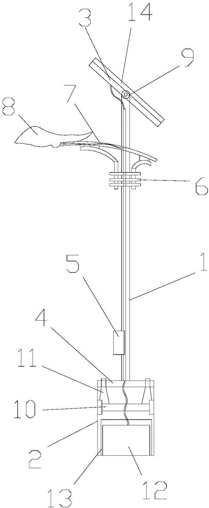
[0025] refer to figure 1 As shown, a garden solar lighting device includes a light pole 1, a pre-embedded seat 2 and a fixed frame 3, the lower end of the light pole 1 is provided with a fixed plate 4 and a control seat 5, and the fixed plate 4 is connected to the light pole 1 welding, the control 5 is fixed on the side of the light pole 1, the upper end of the light pole 1 is provided with a lamp holder 6, the lamp holder 6 is provided with a bracket 7, and the left end of the bracket 7 is provided with an LED lamp Body 8, the LED lamp body 8 is fixed with the bracket 7, the upper end of the light pole 1 is provided with a hinged seat 9, the embedded seat 2 is located at the bottom of the light pole 1, and the embedded seat 2 is provided with A battery box 10 and a battery 12, the battery box 10 is provided with studs 11 above, the battery 12 is located below the battery box 10, a battery box 13 is provided outside the battery 12, and the fixing frame 3 is located on the ligh...

Embodiment 2

[0042] refer to figure 1 As shown, a garden solar lighting device includes a light pole 1, a pre-embedded seat 2 and a fixed frame 3, the lower end of the light pole 1 is provided with a fixed plate 4 and a control seat 5, and the fixed plate 4 is connected to the light pole 1 welding, the control 5 is fixed on the side of the light pole 1, the upper end of the light pole 1 is provided with a lamp holder 6, the lamp holder 6 is provided with a bracket 7, and the left end of the bracket 7 is provided with an LED lamp Body 8, the LED lamp body 8 is fixed with the bracket 7, the upper end of the light pole 1 is provided with a hinged seat 9, the embedded seat 2 is located at the bottom of the light pole 1, and the embedded seat 2 is provided with A battery box 10 and a battery 12, the battery box 10 is provided with studs 11 above, the battery 12 is located below the battery box 10, a battery box 13 is provided outside the battery 12, and the fixing frame 3 is located on the ligh...

Embodiment 3

[0059] refer to figure 1 As shown, a garden solar lighting device includes a light pole 1, a pre-embedded seat 2 and a fixed frame 3, the lower end of the light pole 1 is provided with a fixed plate 4 and a control seat 5, and the fixed plate 4 is connected to the light pole 1 welding, the control 5 is fixed on the side of the light pole 1, the upper end of the light pole 1 is provided with a lamp holder 6, the lamp holder 6 is provided with a bracket 7, and the left end of the bracket 7 is provided with an LED lamp Body 8, the LED lamp body 8 is fixed with the bracket 7, the upper end of the light pole 1 is provided with a hinged seat 9, the embedded seat 2 is located at the bottom of the light pole 1, and the embedded seat 2 is provided with A battery box 10 and a battery 12, the battery box 10 is provided with studs 11 above, the battery 12 is located below the battery box 10, a battery box 13 is provided outside the battery 12, and the fixing frame 3 is located on the ligh...


PUM


Abstract

The invention discloses a solar lighting device for gardens. The device comprises a lamp post, an embedded seat and a fixing bracket; the lower end of the lamp post is provided with a fixing plate and a control seat, the fixing plate is welded to the lamp post, and the control seat is fixed to the side of the lamp post; the upper end of the lamp post is provided with a lamp holder, the lamp holder is provided with a support, the left end of the support is provided with an LED lamp body which is fixed to the support, and the upper end of the lamp post is further provided with a hinge seat; the embedded seat is located at the bottom of the lamp post, a battery box and a storage battery are arranged in the embedded seat, studs are arranged on the battery box, the storage battery is located under the battery box, and the battery box is arranged outside the storage battery; the fixing bracket is located over the lamp post, hinged to the hinge seat and provided with a solar panel. The solar lighting device for the gardens is simple in structure, environmentally friendly, economical in energy and convenient to maintain, and the battery box has the advantages of being moistureproof, waterproof and long in service life.

Description

technical field [0001] The invention specifically relates to a garden solar lighting device. Background technique [0002] Now there are many gardens that are usually open at night. When people are tired from walking in the gardens and need to sit down and rest, they are usually dark. Now some gardens are equipped with lighting devices, but usually this kind of lighting devices Usually it needs to be turned on manually. If the light is not turned off, it will not only waste electric energy, but also greatly reduce the service life of the lighting. The structure is complicated and the design is unreasonable. Moreover, due to the large area of ​​the garden, There are too many lighting devices, and the power consumption increases accordingly. However, most of the existing lighting devices are directly connected to the power supply, which consumes a lot of power and is not environmentally friendly. Moreover, although the existing solar lighting devices can save The effect of el...

Claims


Application Information

Patent Timeline
IPC IPC(8): F21S9/03F21V21/10H02S20/30F21W131/109F21Y115/10
CPCF21S9/035F21V21/10F21W2131/109H02S20/30Y02B20/72Y02E10/50
Inventor 张日龙
Owner 张日龙
Why Eureka
Try Eureka