Capacitor production positioning device

A positioning device and capacitor technology, which is applied in packaging capacitor devices, capacitors, capacitor manufacturing, etc., can solve the problems of positioning offset, inconvenient installation and positioning operations, and different height positions, and achieve high production efficiency and high one-time pass rate. , Positioning the effect of high verticality

Active Publication Date: 2016-10-12
宁波新容电器科技有限公司
View PDF5 Cites 1 Cited by
  • Summary
  • Abstract
  • Description
  • Claims
  • Application Information

AI Technical Summary

Problems solved by technology

[0003] The present invention provides a solution to solve the current situation that in the production process of epoxy encapsulation of high-current capacitors used in existing electric power systems, the installation and positioning of the lead-out terminals of the capacitor electrodes is inconvenient, the positi

Method used


Image

  • Capacitor production positioning device
  • Capacitor production positioning device
  • Capacitor production positioning device

Examples


Embodiment 2

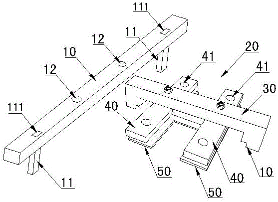
[0023] Figure 5 In the shown embodiment, the electrode base fixing plate 50 for fixing the capacitor electrode lead-out terminal base is provided under the electrode lead-out terminal positioning plate 30, and the electrode base fixing plate 50 is provided with four square holes 51 for fixing and fixing the capacitor electrode lead-out terminal base , the distribution of the four square holes 51 is aligned with the guide limit hole of the electrode lead-out terminal located above, and the bottom end of the capacitor electrode lead-out terminal is installed and fixed in the square hole 51, which not only quickly and effectively locates the position of the electrode lead-out terminal but also It quickly and effectively ensures the height and dimension consistency of the packaged capacitor electrode lead-out terminals in terms of the height of the lead-out terminals, prevents unevenness of each electrode lead-out terminal of the packaged capacitor, and effectively improves the ov...

Embodiment 3

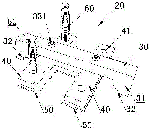
[0025] Positioning bar 10 two ends places are provided with rectangular vertical arm mounting hole, and the length direction of vertical arm mounting hole is consistent with the lengthwise direction of positioning bar, and the limit vertical arm upper end is slidably located in the rectangular vertical arm mounting hole, vertical The arm mounting hole is provided with a sliding limit groove on the upper end of the limit vertical arm in the length direction, and a compression spring is arranged in the rectangular vertical arm mounting hole on the outer side of the positioning rod. One end of the compression spring touches the upper end of the limit vertical arm and the other One end touches the mounting hole of the vertical arm to form an installation connection structure in which the distance between the two limiting vertical arms at the two ends of the positioning rod is adjustable. Others are identical with embodiment 1 or embodiment 2.


PUM


Abstract

The invention discloses a capacitor production positioning device, which comprises a length positioning mechanism and a width positioning mechanism. The length positioning mechanism comprises a positioning rod. The middle portion of the positioning rod is provided with two first positioning through holes. The two first positioning through holes are corresponding to space between capacitor electrode leading-out terminals in the length direction; downward limit vertical arms are arranged close to the two ends of the positioning rod; and the distance between the inner side surfaces of the two limit vertical arms is in limit cooperation with the distance of housing outer walls of a capacitor in the length direction. The width positioning mechanism comprises a positioning pressing plate and an electrode leading-out terminal positioning plate arranged under the positioning pressing plate. The two ends of the positioning pressing plate are downwardly and respectively connected with a limit positioning block with a trapezoid limit positioning step. The two trapezoid limit positioning steps jointly form a limit positioning member of the capacitor in the width direction. Effective and quick production positioning and limit of the electrode leading-out terminals in the length direction and width direction are realized; the electrode leading-out terminals are positioned accurately and do not deviate; the production efficiency is high; and one-time qualified rate is high.

Description

technical field [0001] The invention relates to a capacitor structure, in particular to a production positioning device used for packaging and positioning capacitors. Background technique [0002] In the high-current and high-capacity capacitors used in electric power systems, the capacitor shells and capacitor electrode lead-out terminals used are large in size. It is necessary to install the capacitors in the large-sized capacitor shells and then use epoxy for packaging, and this Before epoxy encapsulation, it is necessary to perform good positioning and fixing operations on the capacitor and its electrode lead-out terminals in order to meet the packaging production quality requirements; usually in the conventional packaging of this type of capacitor, there is the inconvenience of installing and positioning the position of the capacitor electrode lead-out terminals , positioning offset, inconsistent height position, poor consistency and other defects are not conducive to e...

Claims


Application Information

Patent Timeline
IPC IPC(8): H01G13/00
CPCH01G13/003H01G13/006
Inventor 邵智金贾德星陈学燕范丽娜
Owner 宁波新容电器科技有限公司
Why Eureka
Try Eureka