Supercharge Your Innovation With Domain-Expert AI Agents!

A jig for quickly withdrawing drill pins from pcb

It is a quick drill back technology, which is applied in the manufacture of printed circuits, electrical components, and printed circuits. It can solve problems such as difficult manual extraction, small diameter of drill needles, and damage caused by drill needles. It achieves simple structure, improved efficiency, and avoids pop-up effect

Active Publication Date: 2018-10-09
广东喜珍电路科技有限公司
View PDF4 Cites 0 Cited by
  • Summary
  • Abstract
  • Description
  • Claims
  • Application Information

AI Technical Summary

Problems solved by technology

The drill cutter head of the Schmoll machine is suspended under the drilling rig table, and there are several magazine rows for hanging drill needles. Each magazine can arrange 11 drill needles; the magazine is designed with a silicone collar to fix the drill needles. Prevent the drill needle from falling off; however, the new drill needle or the new cartridge is very tight when it is first used, and it is not easy to pull it out manually. In addition, the diameter of the existing drill needle is getting smaller and smaller (minimum 0.10mm). In the production of mechanical drilling, the drill needle When preparing materials, it is necessary to withdraw the drill needle from the magazine (or pull out the drill needle). Occasionally, the drill needle will be stabbed, or even the broken needle cannot be taken out normally in the muscle, and the work-related accidents can only be operated.
[0003] At present, the preparation of this type of mechanical drilling needles in the PCB industry basically adopts the traditional manual operation method. First, insert the drilling needles into the magazine one by one. Pull out one by one to grind drills and reuse magazines; this operation method is extremely inefficient, and accidents inevitably occur from time to time

Method used


Image

  • A jig for quickly withdrawing drill pins from pcb
  • A jig for quickly withdrawing drill pins from pcb
  • A jig for quickly withdrawing drill pins from pcb

Examples


Embodiment

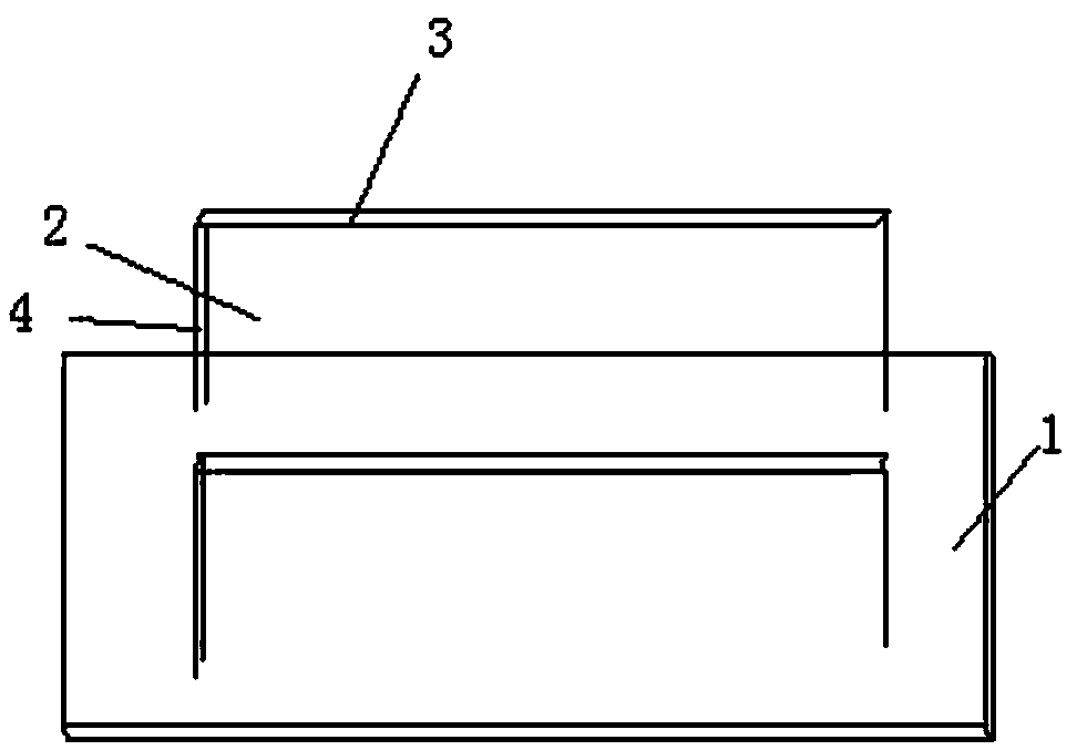
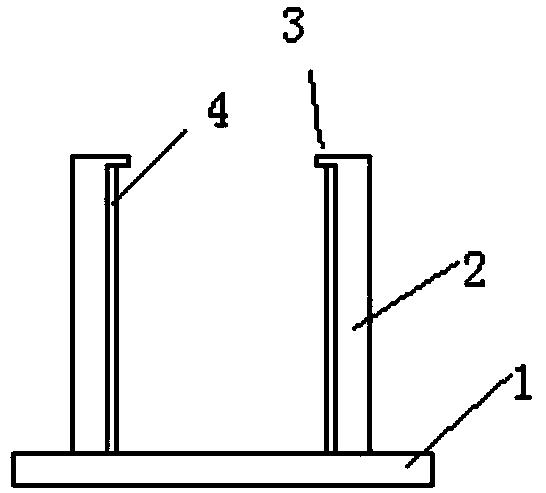
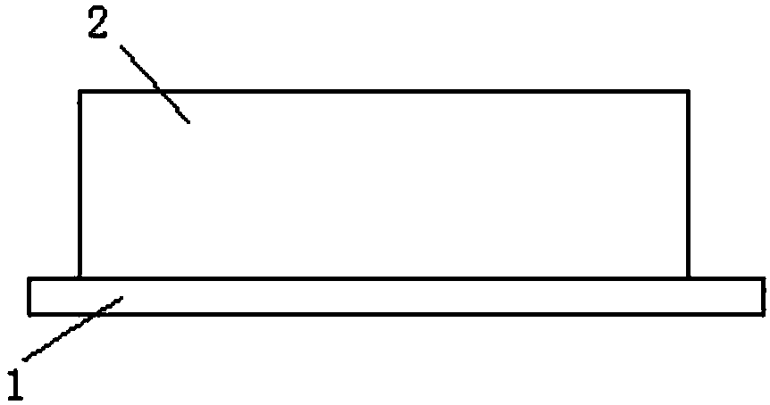
[0016] see figure 1 - image 3 , this embodiment includes a horizontal plate 1, two side plates 2 are arranged on the horizontal plate 1, the two side plates 2 are arranged oppositely, one side plate 2 is fixedly connected with the horizontal plate 1, and the side plate 2 and the side plate can be flexibly adjusted. The distance between the boards 2 expands the scope of application. The front ends of the two side boards 2 are provided with a horizontal baffle 3, and one side of the two side boards 2 is oppositely provided with a vertical baffle 4, which effectively prevents the drill needle magazine from popping up and tying. On the upper arm, the width of the side plate 2 is adapted to the length of the drill, the distance between the two horizontal baffles 3 is less than the diameter of the collar at the upper end of the drill, and the length of the horizontal plate 1 is the same as the drill of the drill clip. The needle capacity is adapted, the length of the side plate 2 ...


PUM


Abstract

The invention provides a PCB fast drill point retracting tool which comprises a horizontal plate. Two side plates are arranged on the horizontal plate. Two side plates are arranged opposite to each other. One side plate is fixedly connected with the horizontal plate. Horizontal baffles are arranged on the front end of two side plates. Vertical baffles are arranged on opposite sides of two side plates. The width of the side plates matches the length of a drill point. The distance between two horizontal baffles is smaller than the diameter of a shrink-ring on the upper end of the drill point. The length of the horizontal baffles matches the drill point capacity of a drill point clip. The length of the side plates is smaller than the length of the horizontal plates. The length of the horizontal baffles matches the length of the side plates. The length of the vertical baffles is the same as the width of the side plates. According to the invention, the PCB fast drill point retracting tool has the advantages of simple structure, clever design, fast drill point retracting, and being safe and reliable, and is suitable for industrial production and application; the efficiency of drill point retracting in drilling production preparation is greatly improved; and work-related accidents can be effectively avoided.

Description

technical field [0001] The invention relates to the processing of drill pins of PCB mechanical drilling tools, in particular to a jig for quickly withdrawing drill pins from PCBs. technical background [0002] In the existing mature management system of PCB mechanical drilling, the diameter of the drill needle is very small. The design of the drill needle and cutterhead on the drilling machine is completely different for the two models with the best reputation in the PCB industry, HITACHI and Schmoll. Yes, in contrast, each has its own merits. The drill cutter head of the Schmoll machine is suspended under the drilling rig table, and there are several magazine rows for hanging drill needles. Each magazine can arrange 11 drill needles; the magazine is designed with a silicone collar to fix the drill needles. Prevent the drill needle from falling off; however, the new drill needle or the new cartridge is very tight when it is first used, and it is not easy to pull it out manu...

Claims


Application Information

Patent Timeline
Patent Type & Authority Patents(China)
IPC IPC(8): H05K3/00
CPCH05K3/0047H05K2203/0221
Inventor 陈志新贺文辉罗新权周毅
Owner 广东喜珍电路科技有限公司
Features
  • R&D
  • Intellectual Property
  • Life Sciences
  • Materials
  • Tech Scout
  • Unparalleled Data Quality
  • Higher Quality Content
  • 60% Fewer Hallucinations
Learn More